
Flat type vibration motor

a vibration motor and flat-type technology, applied in mechanical energy handling, dispersed particle separation, separation processes, etc., can solve the problems of degrading workability, affecting the operation efficiency, so as to prevent any stoppage in initialization or operation, efficient and stable initialization and operation

Inactive Publication Date: 2005-08-25
SAMSUNG ELECTRO MECHANICS CO LTD
View PDF25 Cites 5 Cited by
  • Summary
  • Abstract
  • Description
  • Claims
  • Application Information

AI Technical Summary

Benefits of technology

[0021] The present invention has been made to solve the foregoing problems of the prior art and it is therefore an object of the present invention to provide a flat type vibration motor capable of preventing any stoppage in the initialization or operation thereof to realize efficient and stable initialization and operation.
[0022] It is another object of the invention to provide a flat type vibration motor capable of incorporating a single winding coil in a rotor to simplify an assembly process and save manufacturing cost.

Problems solved by technology

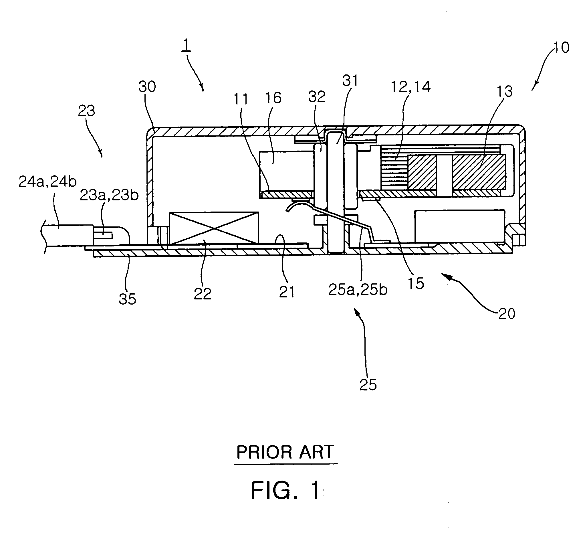
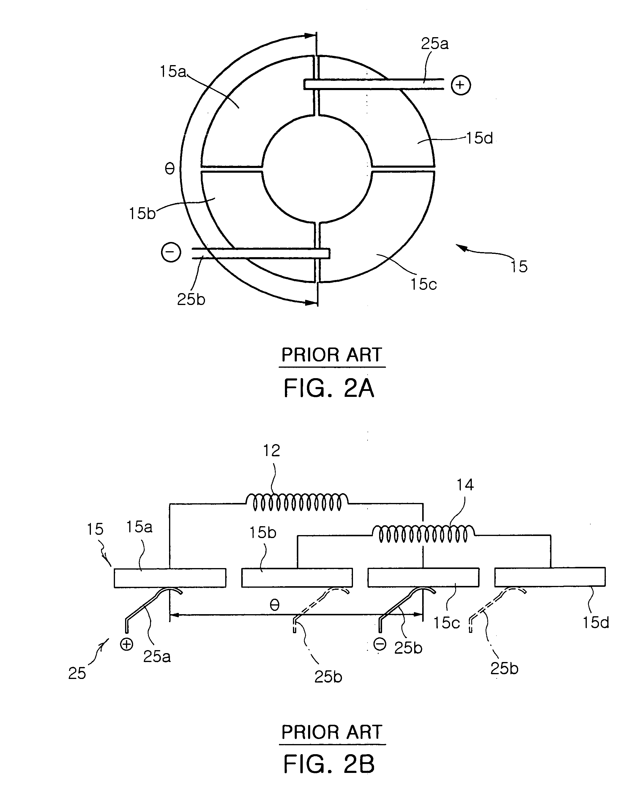
Then, a dead point as an electrically disconnected section for temporarily interrupting power supply takes place to bring a temporary or complete stoppage to the initialization or operation of the motor, thereby producing a fatal problem of disabling the motor.
However, according the conventional scheme of forming the neutral point N through the double winding of the winding coils 12 and 14, respectively, to prevent the dead point, because the winding coils 12 and 14 are double-wound with a winder (not shown), and then the double coils 12a, 12b, 14a and 14b of the winding coils 12 and 14 are necessarily arranged by a worker, the winding and arranging operations become very troublesome to degrade workability as well as increase coil consumption thereby to raise manufacturing cost.

Method used


Image

  • Flat type vibration motor
  • Flat type vibration motor
  • Flat type vibration motor

Examples


Embodiment Construction

[0054] Preferred embodiments of the present invention will now be described in detail with reference to the accompanying drawings.

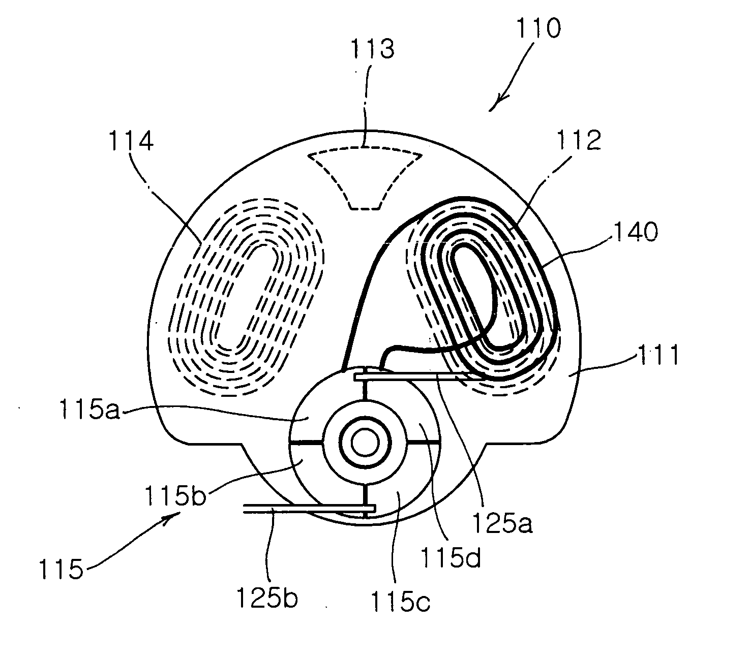
[0055]FIG. 4 is an exploded perspective view illustrating a flat type vibration motor according to a first embodiment of the invention, FIG. 5 is a bottom view of a rotor adopted in the flat type vibration motor according to the first embodiment of the invention, and FIGS. 6A and 6B are illustrations of the flat type vibration motor according to the first embodiment of the invention, in which FIG. 6A illustrates a brush in normal contact with a rectifier, and FIG. 6B illustrates the brush in abnormal contact with the rectifier disabling the operation of the vibration motor.

[0056] As shown in FIG. 4, a flat type vibration motor 100 of the invention includes a rotor 110, a stator 120 and a housing 130 in order to generate vibration by using lateral pressure induced from a shaft 131 when the eccentric rotor 110 rotates about the stator 120 at the applicati...


PUM

PropertyMeasurementUnit
electrical angleaaaaaaaaaa
voltageaaaaaaaaaa

Abstract

Disclosed is a flat type vibration motor, in which a shaft is supported between a housing and a bracket. A rotor includes an upper board, A and B phase winding coils, an eccentric weight and a rectifier. The rectifier has a plurality of segments electrically connected to first and second ends of the A and B phase winding coils. A stator includes a lower board, a magnet and a pair of brush fingers electrically connected to a power supply and in contact with the segments. A pattern coil on the upper board electrically connects between a segment connected to a first end of the A phase winding coil and another segment connected to a second end of the B phase winding coil to generate electromagnetic force for rotating the rotor from an electrically disconnected section to an electrically connected section.

Description

CLAIM OF PRIORITY [0001] This application claims the benefit of Korean Patent Application No. 2004-12510 filed on Feb. 25, 2004, in the Korean Intellectual Property Office, the disclosure of which is incorporated herein by reference. BACKGROUND OF THE INVENTION [0002] 1. Field of the Invention [0003] The present invention relates to a flat type vibration motor, more particularly, which is so structured to prevent any stoppage in the initialization or operation thereof to realize efficient and stable initialization and operation. The present invention also relates to a flat type vibration motor capable of incorporating a single winding coil therein to simplify an assembly process thereby saving labor cost and material cost as well as simplify an assembly structure thereby saving manufacturing cost. [0004] 2. Description of the Related Art [0005] Communication instruments generally use bells and vibrators to inform users of call incoming. In a vibration mode, a small-sized vibration m...

Claims


Application Information

Patent Timeline
Patent Type & Authority Applications(United States)
IPC IPC(8): H02K7/06H02K7/065H02K11/02H02K13/10
CPCH02K7/063H02K13/105H02K11/028B01D47/06B01D53/78B05B7/0433B05B7/0458B05B13/0278
Inventor WON, SUNG HONG
Owner SAMSUNG ELECTRO MECHANICS CO LTD
Learn More