
Quick assembly adjustable shelf and drawer system

a shelf and drawer system technology, applied in the field of shelves and drawer systems and brackets, can solve the problems of limited ability to withstand shear forces, fatigue of supporting walls, and failure of supporting walls, and achieve the effects of minimizing moments and shear forces, quick adjustment of shelves, and high load bearing capacity

Inactive Publication Date: 2005-08-25
BONANNO RONALD J
View PDF45 Cites 18 Cited by
  • Summary
  • Abstract
  • Description
  • Claims
  • Application Information

AI Technical Summary

Benefits of technology

[0006] It is an object of the present invention to overcome the drawbacks and shortcomings of conventional wood shelf and drawer systems while allowing the versatility of a quick adjustability of shelves and drawers to meet the changing demands of a user. Particularly, conventional wood shelf and drawer systems do not provide a means of quick adjustable assembly and high load bearing capacity. Many conventional wood shelf systems incorporate a hole in a support wall with a dowel or peg fitted into the hole to support a shelf. The loading and moments caused by shelves on the above mentioned support devices will cause the supporting walls to fatigue and eventually fail at the top of the hole. The design of conventional support devices converts loads into moments. These moments place a shear force on materials with great capacity to support compression forces, but with limited ability to withstand shear forces. The present invention places loads in compression on a supporting wall and on the shelf itself while minimizing moments and shear forces. Prior systems and devices sacrifice load bearing capacity for quick adjustable assembly or they sacrifice the quick adjustable assembly for more load bearing capacity. Either way, conventional systems are limited in their versatility. The present invention provides a system and devices that allow a user to quickly assemble and adjust both shelves and drawers without sacrificing load bearing capacity.
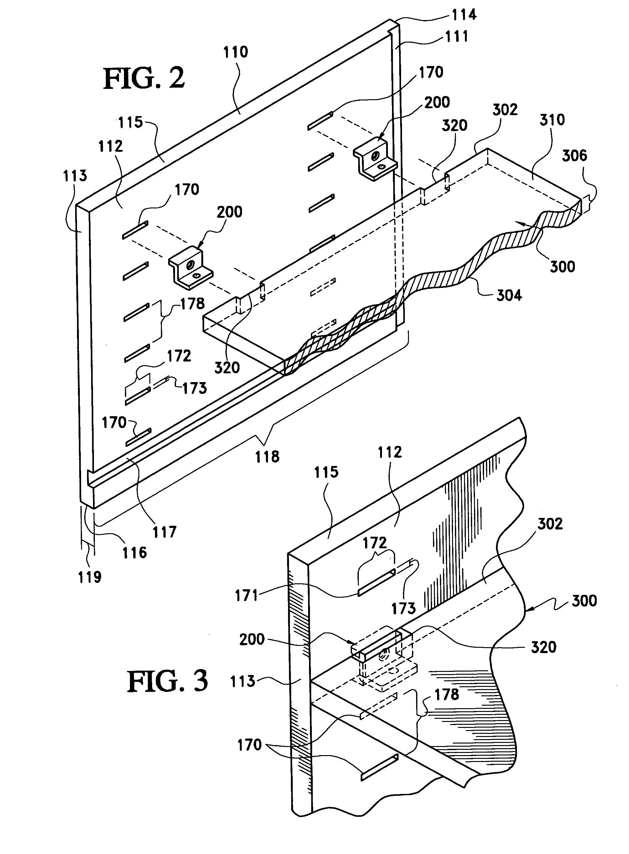
[0014] Further, this invention provides a support device comprising: a vertical member having first and second surfaces and being engageable with a notch disposed on an end of a shelf; a first horizontal member attached to the first surface of the vertical member and being engageable with a horizontal cavity of a wall; and, a second horizontal member attached to second surface of the vertical member at a vertical distance from the first horizontal member and being disposable adjacent to a bottom surface of the shelf, wherein the vertical member will prevent sliding of the shelf across the second surface of the vertical member when the first horizontal member is disposed in the horizontal cavity.

Problems solved by technology

Particularly, conventional wood shelf and drawer systems do not provide a means of quick adjustable assembly and high load bearing capacity.
The loading and moments caused by shelves on the above mentioned support devices will cause the supporting walls to fatigue and eventually fail at the top of the hole.
These moments place a shear force on materials with great capacity to support compression forces, but with limited ability to withstand shear forces.
Prior systems and devices sacrifice load bearing capacity for quick adjustable assembly or they sacrifice the quick adjustable assembly for more load bearing capacity.
Either way, conventional systems are limited in their versatility.
Additionally, conventional shelf systems have no means to restrain a shelf in position without the use of fasteners.
An unfastened shelf can slide off its shelf supports creating an unsafe situation.
On conventional systems with shelves that can slide off the shelf support, a span-wise support bracket may not support the shelf because the shelf may not be positioned in the proper location.

Method used


Image

  • Quick assembly adjustable shelf and drawer system
  • Quick assembly adjustable shelf and drawer system
  • Quick assembly adjustable shelf and drawer system

Examples


Embodiment Construction

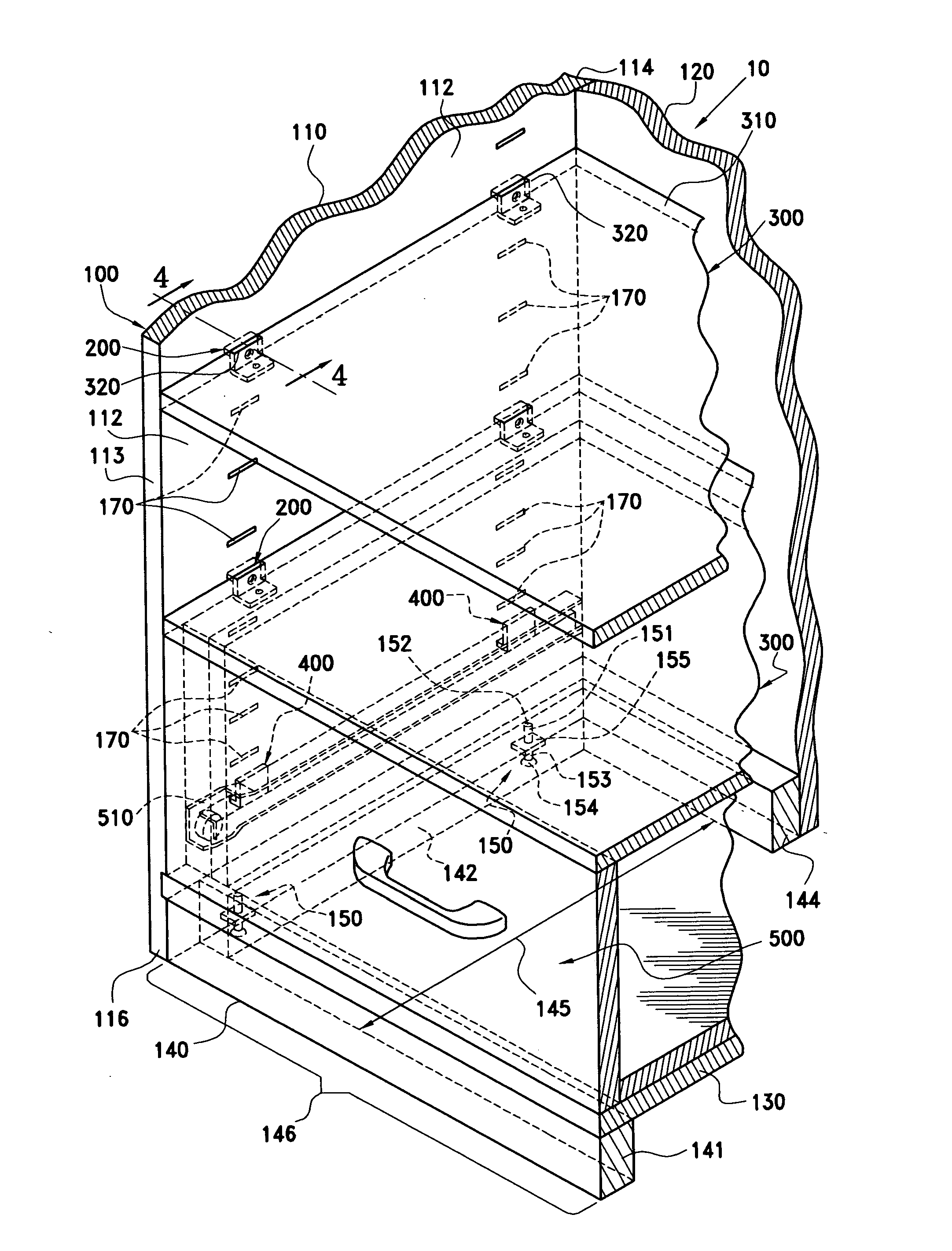
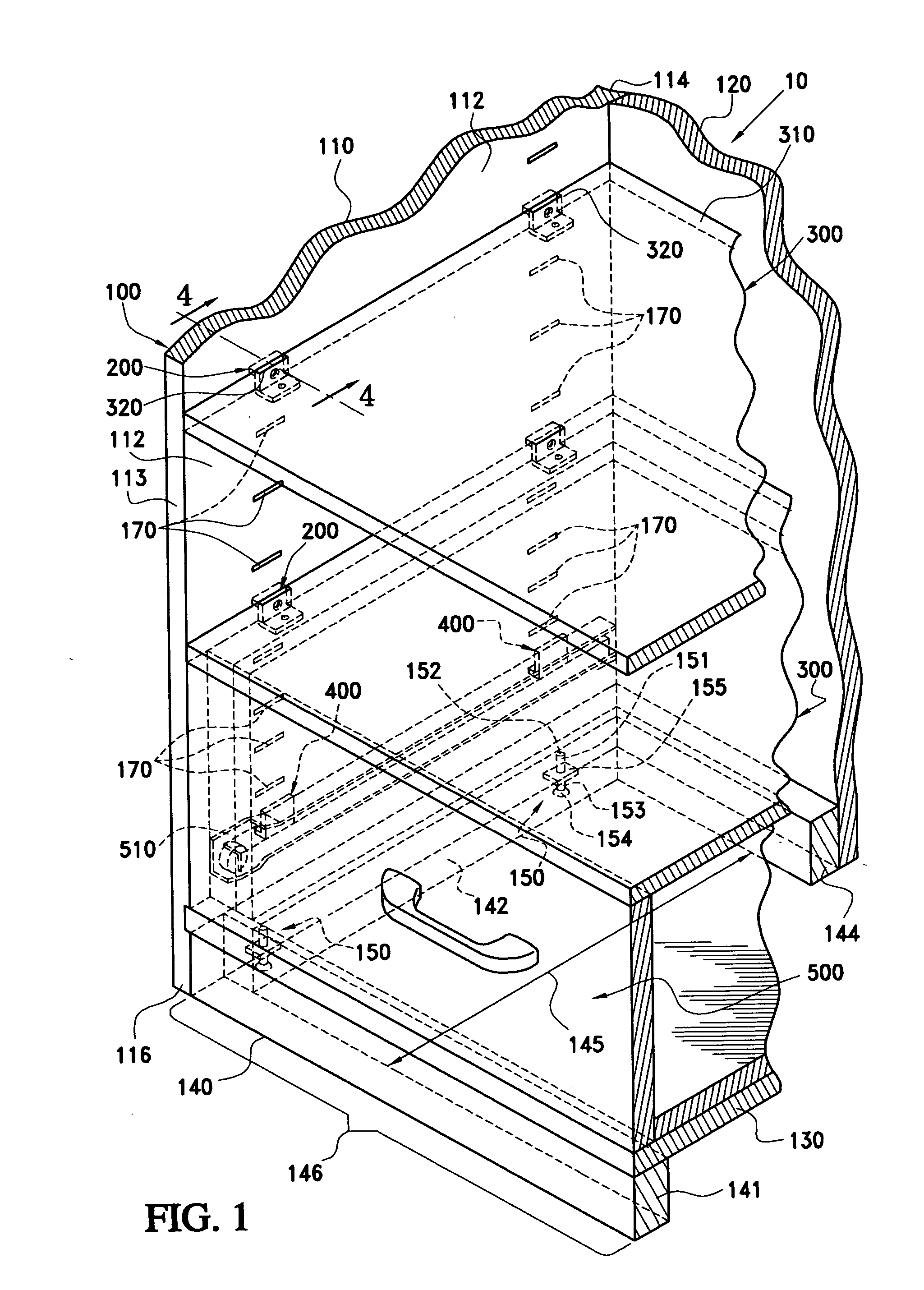
[0031]FIG. 1 is a perspective view of a system 10, which is an exemplary embodiment of a shelf and drawer system made in accordance with this invention. The system 10 is specifically designed to be used in a garage; however, the system 10 may also be used in any environment where shelves and drawers are needed, such as but not limited to closets, kitchens, offices, bathrooms, etc. The system 10 includes a cabinet 100, a plurality of support devices 200, a plurality of shelves 300, a plurality of support brackets 400 and a plurality of drawers 500.

[0032] The system 10, as shown in FIG. 1, is operably configured to provide a means to adjust the placement of the shelves 300 and the drawers 500 by a user in minimum time without sacrificing load bearing capacity. The cabinet 100 is operably configured to receive the support devices 200 and the support brackets 400. The support devices 200, or shelf brackets, are operably configured to removably attach the shelves 300 to the cabinet 100....


PUM


Abstract

The present invention provides a storage system comprising a plurality of support devices each having first, second and third members, wherein the first and third members are connected to the second member. The system also includes a plurality of support brackets having first and second portions connected to each other. Further, two opposing walls each having at least two vertically spaced horizontal cavities, wherein for each of the opposing walls one of the cavities is operably configured to receive the first member of one of the support devices or the second portion of one of the support brackets and the other of the cavities is operably configured to receive the other of the first member and the second portion. The system also includes: a shelf having ends, a bottom surface and at least one notch disposed at each end, wherein the at least one notch is operably configured to receive the second member of one of the support devices, and the bottom surface is disposed adjacent to the third member of at least two of the support devices; and, a drawer having drawer glides disposed at each side wherein each of the drawer glides are attached to the first portion of at least one of the support brackets.

Description

CROSS REFERENCE TO RELATED APPLICATION [0001] This nonprovisional application claims the benefit of Provisional Application No. 60 / 540,495, filed on Feb. 2, 2004, which is incorporated herein by reference in its entirety.BACKGROUND OF THE INVENTION [0002] 1. Field of Invention [0003] The present invention is related to shelf and drawer systems and brackets thereof. [0004] 2. Description of Related Art [0005] The making of wood shelves and draws is an art that in times past was common knowledge to most people. However, through the last century, people have become more urbanized and less accustom with the ways of elementary carpentry. However, the need for shelving and drawers to maximize storage space has remained, but the skill to make them has not. Today, to fill the need for home, closet and garage shelving and drawers, many designers and manufactures have devised shelf and drawer systems. These systems vary from permanent structures to removable units to adjustable units and comb...

Claims


Application Information

Patent Timeline
Patent Type & Authority Applications(United States)
IPC IPC(8): A47B57/32A47B88/04A47B96/04A47B96/06
CPCA47B57/32A47B96/068A47B88/044A47B88/43
Inventor BONANNO, RONALD J.POWNING, DENNIS S.
Owner BONANNO RONALD J
Learn More