
Fixing device for fixing an object to a fixing plate and antenna apparatus using the fixing device

a fixing device and fixing plate technology, applied in the direction of antenna details, antenna adaptation in movable bodies, antennas, etc., can solve the problems of increasing the number of parts, complicated mounting operation, disadvantageous above-mentioned mounting structure using the mounting member, etc., to achieve easy and smooth operation

Active Publication Date: 2005-08-25
MITSUMI ELECTRIC CO LTD
View PDF17 Cites 39 Cited by
  • Summary
  • Abstract
  • Description
  • Claims
  • Application Information

AI Technical Summary

Benefits of technology

The invention provides a fixing device for easily and smoothly fixing an object to a fixing plate. The device includes a first screw member on the object and a second screw member on the fixing member. The fixing member has a bottom plate portion with a through hole for the second screw member and a plurality of spring portions extending from the bottom plate portion. The bottom plate portion has an outer dimension smaller than a fixing hole on the fixing plate, and the spring portions have lateral sides with cut-away portions formed by cutting the lateral sides from the bottom plate portion in one direction. The invention also provides an antenna apparatus using this fixing device.

Problems solved by technology

However, the above-mentioned mounting structure using the mounting member is disadvantageous in the following respects.
Therefore, the number of parts is increased and a mounting operation is complicated.
Thus, it is difficult to perform the mounting operation smoothly.

Method used


Image

  • Fixing device for fixing an object to a fixing plate and antenna apparatus using the fixing device
  • Fixing device for fixing an object to a fixing plate and antenna apparatus using the fixing device
  • Fixing device for fixing an object to a fixing plate and antenna apparatus using the fixing device

Examples


Embodiment Construction

[0026] Now, with reference to the drawing, description will be made of a fixing device for fixing an object to a fixing plate according to this invention. In this embodiment, consideration will be made about an automobile antenna apparatus (hereinafter simply referred to as an antenna apparatus) by way of example.

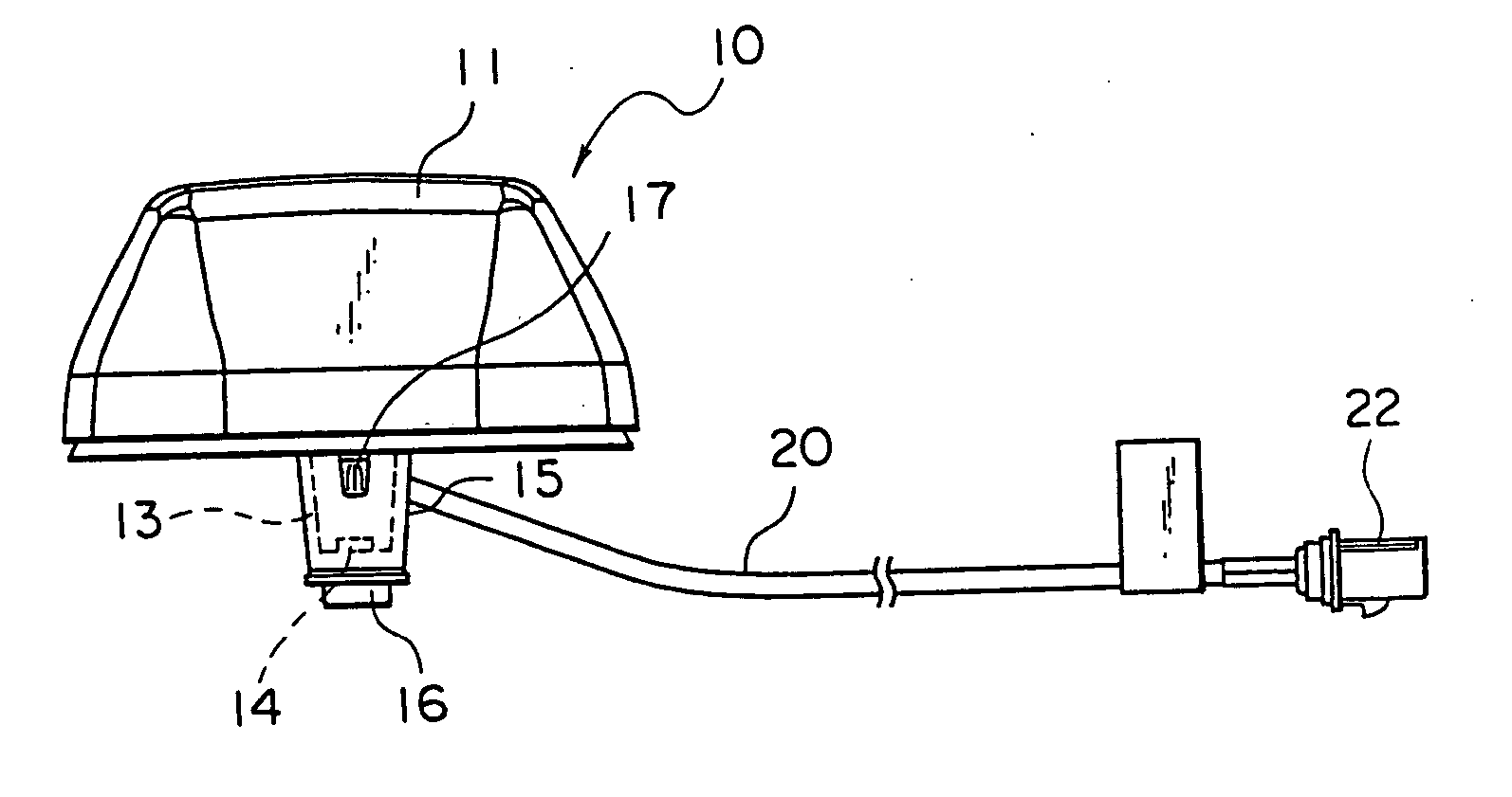
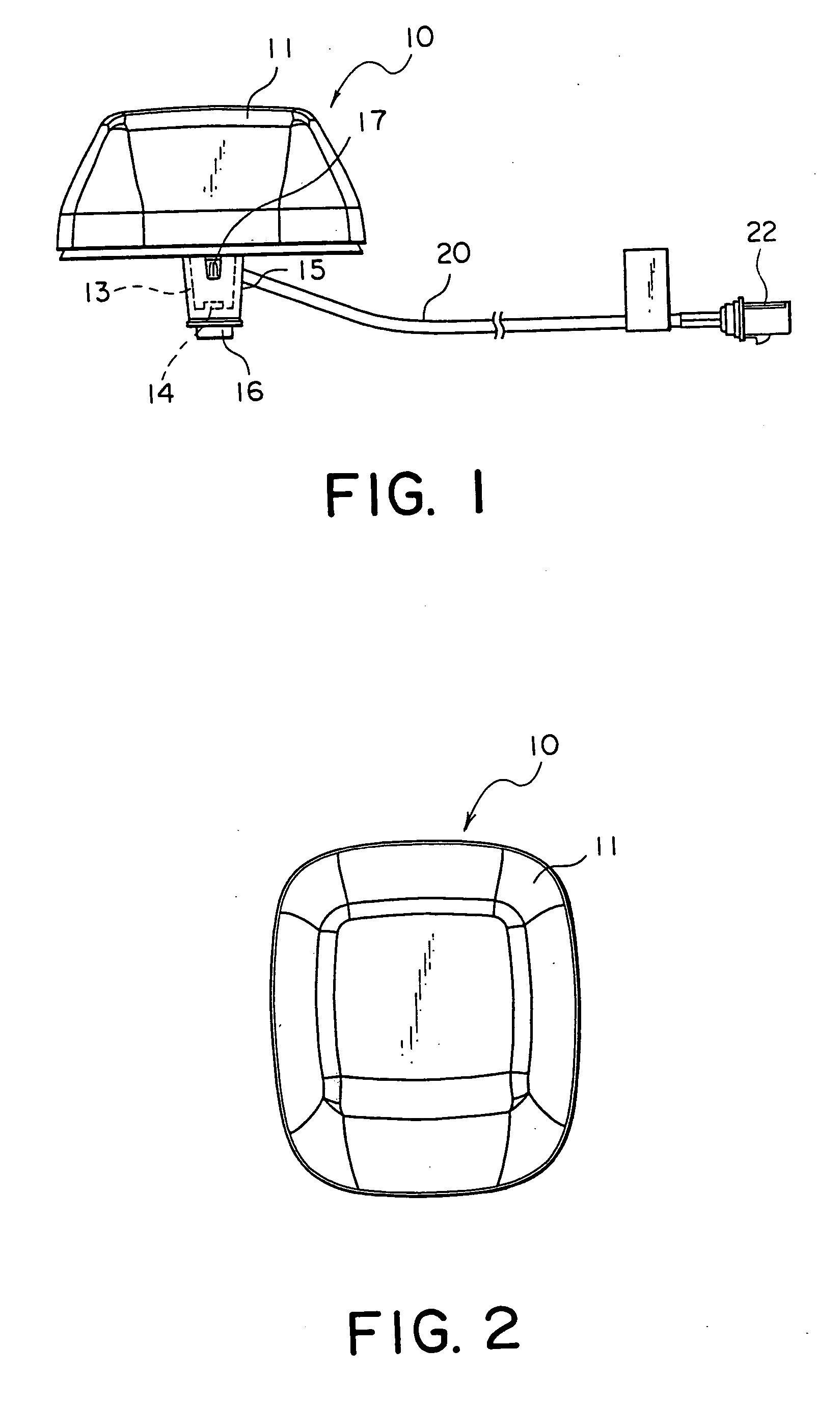
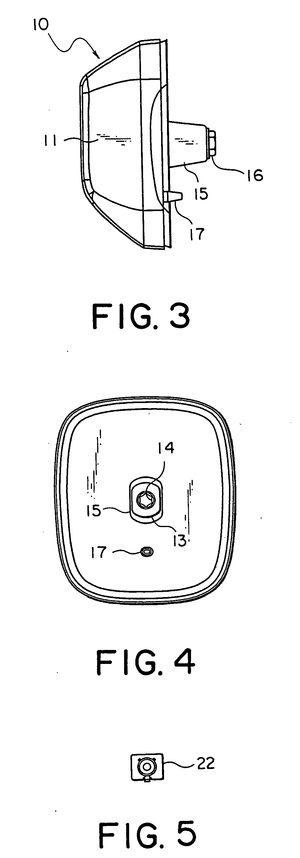
[0027] Referring to FIGS. 1 through 4, an antenna apparatus (object) 10 using a fixing device for fixing an object to a fixing plate comprises a case 11 of a small dome-like shape and a fixing portion 13 integrally formed with the case 11.

[0028] The case 11 contains an antenna element (not shown). The fixing portion 13 is formed at an approximate center of a bottom surface of the case 11 and protrudes downward from the bottom surface. The fixing portion 13 has a female screw (first screw member) 14 formed inside. The fixing portion 13 is covered with a bracket (fixing member) 15. The bracket 15 is fixed to the fixing portion 13 by screw engagement between the female screw...


PUM


Abstract

For fixing an object to a fixing plate by a fixing portion of the object and a fixing member, a fixing device includes a first screw member formed on the object and a second screw member corresponding to the first screw member. The fixing member includes a bottom plate portion provided with a through hole allowing a threaded portion of the second screw member to pass therethrough and a plurality of spring portions extending from the bottom plate portion in one direction. The bottom plate portion has an outer dimension smaller than a fixing hole formed on the fixing plate. A combination of the spring portions extends in the one direction from the bottom plate portion having an outer dimension greater than the fixing hole in at least an upper part thereof. Each of the spring portions has lateral sides provided with cut-away portions formed by cutting the lateral sides from the bottom plate portion in the one direction.

Description

[0001] This application claims priority to prior Japanese patent application JP 2004-45945, the disclosure of which is incorporated herein by reference. BACKGROUND OF THE INVENTION [0002] This inventor, relates to a fixing device for fixing an object to a fixing plate by the use of a screw member and to an antenna apparatus using the fixing device. [0003] Recently, a digital radio receiver adapted to receive a satellite wave or a ground wave so as to listen to digital radio broadcasting is put into practical use. The digital radio receiver is mounted to a mobile station. Specifically, the digital radio receiver is adapted to receive a radio wave having a frequency of about 2.3 GHz as a reception wave. The reception wavelength (resonance wavelength) λ is equal to about 128.3 mm. Thus, the digital radio receiver is capable of listening to the digital radio broadcasting. [0004] Thus, the digital radio receiver is a radio receiver adapted to listen to mobile broadcasting. The ground wav...

Claims


Application Information

Patent Timeline
Patent Type & Authority Applications(United States)
IPC IPC(8): H01Q1/22H01Q1/12H01Q1/27H01Q1/32
CPCH01Q1/3275H01Q1/1214
Inventor SAITO, YUICHISATO, KYUICHI
Owner MITSUMI ELECTRIC CO LTD
Learn More