Catadioptric projection objective with geometric beam splitting

a technology of geometric beams and projection objectives, applied in the field of catadioptric projection objectives, can solve problems such as polarization problems and physical space problems

Inactive Publication Date: 2005-08-25
CARL ZEISS SMT GMBH
View PDF23 Cites 554 Cited by
  • Summary
  • Abstract
  • Description
  • Claims
  • Application Information

AI Technical Summary

Benefits of technology

[0016] The invention is based on the object of providing a catadioptric projection objective which allows imaging errors to be corrected well, while having an advantageous physical for...

Problems solved by technology

However, the form of the refractive design is governed by two elementary imaging errors: the chromatic correction and correction for the Petzval sum (image field curvature).
One disadvantage of the catadioptric design is, however, that it is necessary to wor...

Method used


Image

  • Catadioptric projection objective with geometric beam splitting
  • Catadioptric projection objective with geometric beam splitting
  • Catadioptric projection objective with geometric beam splitting

Examples


first embodiment

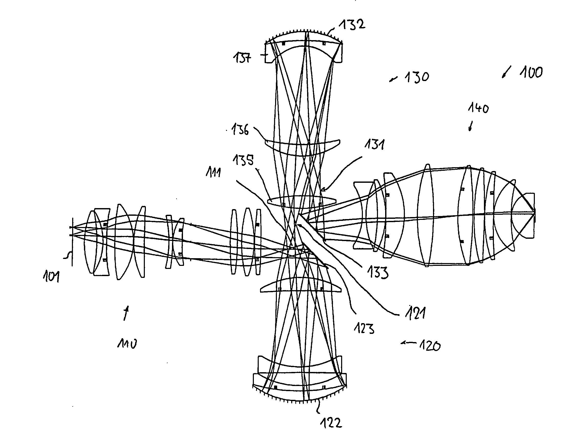
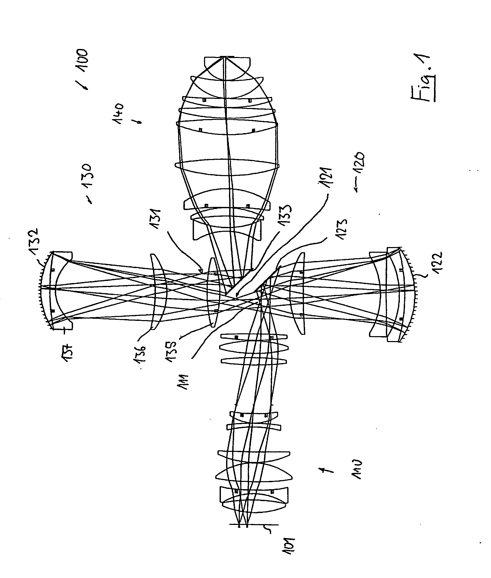
[0058]FIG. 1 shows a lens section through a projection objective 100 which has a cruciform structure and has two coaxial catadioptric objective parts as well as two refractive objective parts which are arranged on the input side and output side of the objective. This is used to image a pattern, which is arranged on its object plane 101, of a mask on a reduced scale on its image plane 102, which is aligned parallel to the object plane. It comprises a first, refractive objective part 110, which images the object field in a first, real intermediate image 111, a second, catadioptric objective part 120 which images the first intermediate image in a second real intermediate image 121, a third, likewise catadioptric objective part 130, which images the second intermediate image in a real third intermediate image, and a fourth, refractive objective part, which images the third intermediate image 131 on the image plane 102 on a reduced scale. Each of the catadioptric objective parts has a co...

fourth embodiment

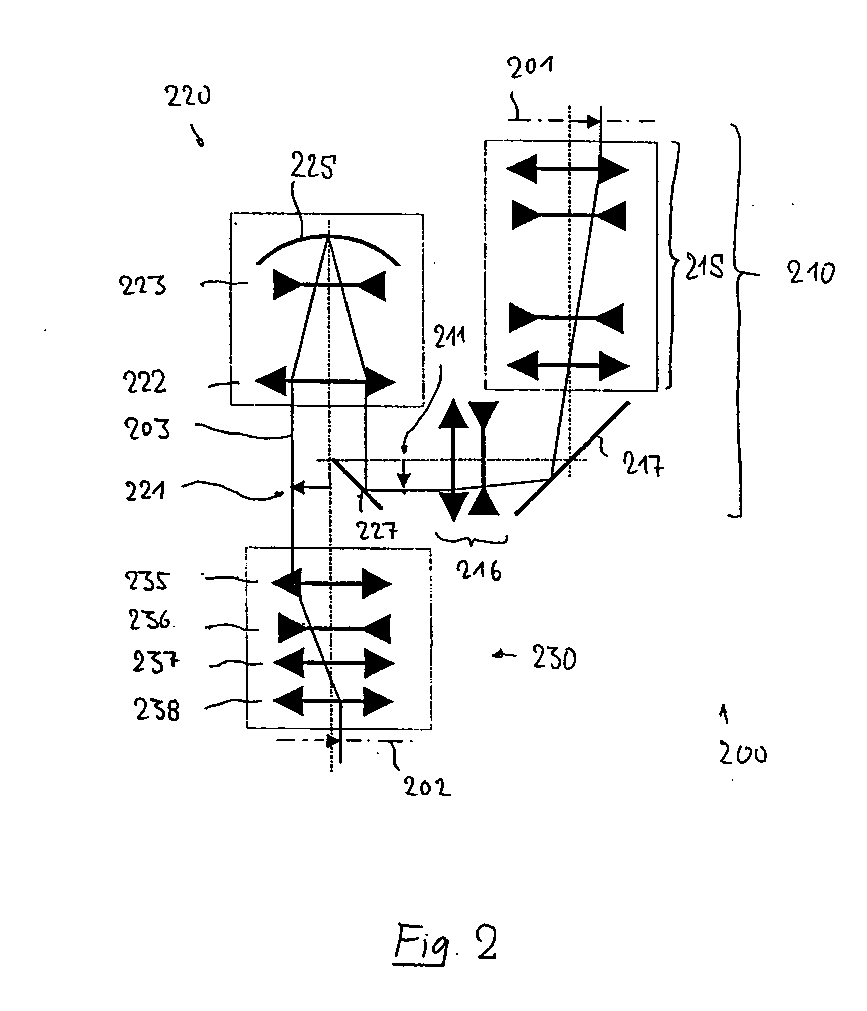
[0090]FIG. 4 shows the projection objective 400. Identical or corresponding elements or element groups are annotated with the same reference symbols as in FIG. 2, increased by 200.

[0091] The refractive first objective part 410 images the object field on a first intermediate image 411, which is located downstream from the first folding mirror 417 in the beam direction. This is thus arranged within the first refractive objective part 410, in its end area. The catadioptric objective part 420 images the first intermediate image 411 on a second intermediate image 421, which is located geometrically between a mirror edge close to the axis of the first folding mirror 417 and the object plane, in the immediate vicinity of this mirror edge. The second intermediate image is imaged by a third, refractive objective part 430 on the image plane 402, without any further intermediate image. This objective part has a second folding mirror 427 arranged between the first and the last lens of the objec...


PUM


Abstract

A catadioptric projection objective for imaging a pattern arranged on the object plane of the projection objective, on the image plane of the projection objective, comprising: a first objective part for imaging an object field in a first real intermediate image; a second objective part for producing a second real intermediate image with the radiation coming from the first objective part; and a third objective part for imaging the second real intermediate image on the image plane; wherein at least one of the objective parts is a catadioptric objective part with a concave mirror, and at least one of the objective parts is a refractive objective part and a folding mirror is arranged within this refractive objective part in such a way that a field lens is arranged between the folding mirror and an intermediate image which is closest to the folding mirror.

Description

BACKGROUND TO THE INVENTION [0001] 1. Field of the Invention [0002] The invention relates to a catadioptric projection objective for imaging a pattern arranged on the object plane of the projection objective, on the image plane of the projection objective. [0003] 2. Description of the Related Prior Art [0004] Projection objectives such as these are used in microlithography projection exposure systems for producing semiconductor components and other finely structured components. They are used to project patterns of photomasks or reticles, which are referred to in a generalized form in the following text as masks or reticles, onto an object which is coated with a light-sensitive layer, with very high resolution and on a reduced scale. [0005] In this case, in order to produce ever finer structures, the numerical aperture (NA) of the projection objective on the image side must on the one hand be increased and, on the other hand, ever-shorter wavelengths must be used, preferably ultravio...

Claims


Application Information

Patent Timeline
IPC IPC(8): G02B1/00G02B17/00G02B17/08G02B21/00G02B23/00G03F7/20
CPCG02B17/08G03F7/70225G02B17/0892G02B17/0804
Inventor EPPLE, ALEXANDERBEIERL, HELMUTDODOC, AURELIANULRICH, WILHELM
Owner CARL ZEISS SMT GMBH
Why Eureka
Try Eureka