Backlight system

a backlight system and backlight technology, applied in the field of backlight systems, can solve problems such as discomfor

Inactive Publication Date: 2005-08-25
CITIZEN ELECTRONICS CO LTD
View PDF6 Cites 4 Cited by
  • Summary
  • Abstract
  • Description
  • Claims
  • Application Information

AI Technical Summary

Benefits of technology

[0009] Therefore, an object of the present invention is to resolve the above-mentioned problems and to provide a backlight system capable of equalizing the directivities of light in the length and width directions of the backlight system.

Problems solved by technology

The differences in brightness in an LCD which uses a backlight system having a difference in the directivities of light between its length and width directions causes a feeling of discomfort and this has been a problem.

Method used


Image

  • Backlight system
  • Backlight system
  • Backlight system

Examples


Embodiment Construction

[0023] Preferred embodiments of the present invention will be explained with reference to the accompanying drawings below.

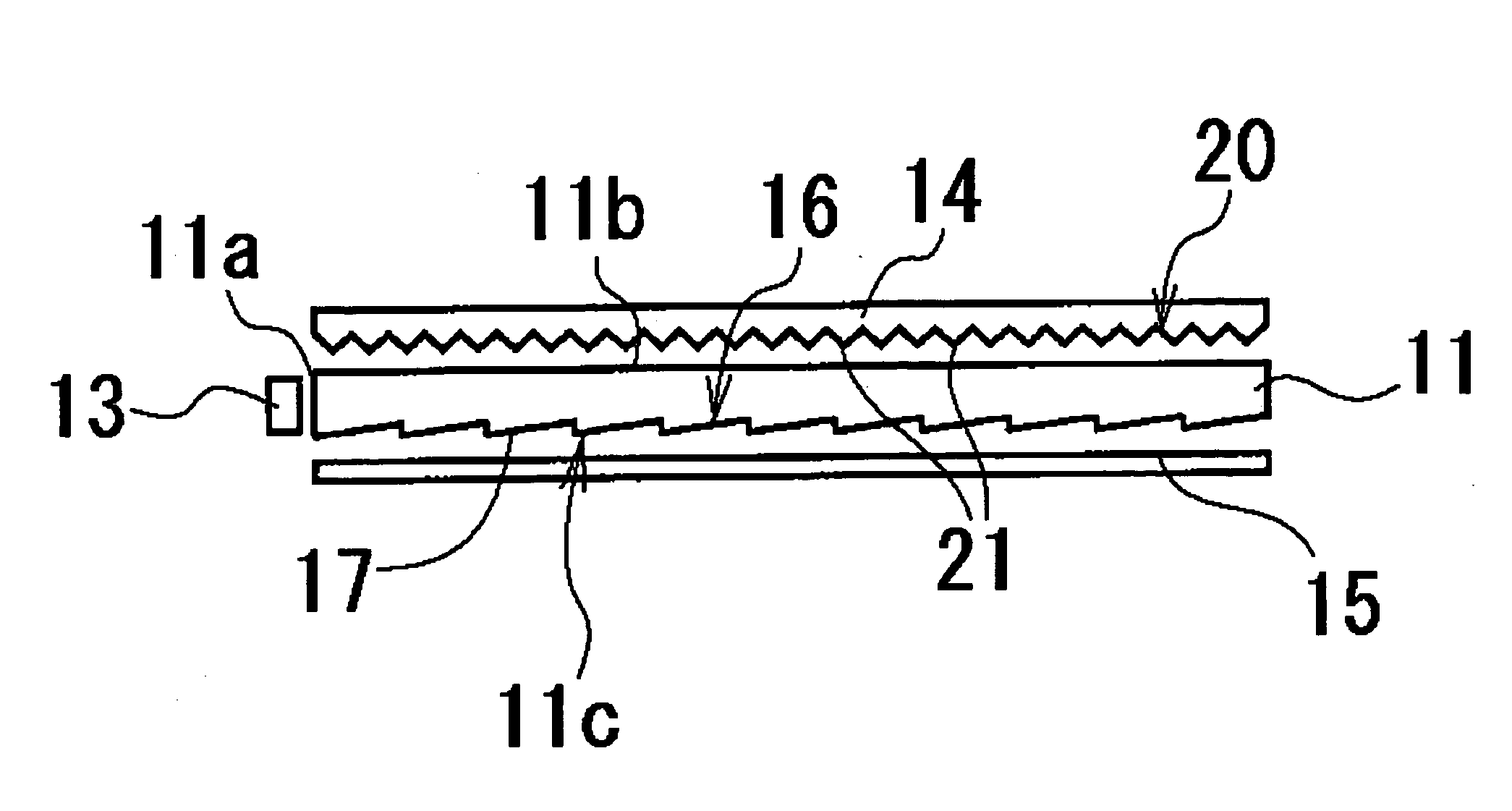
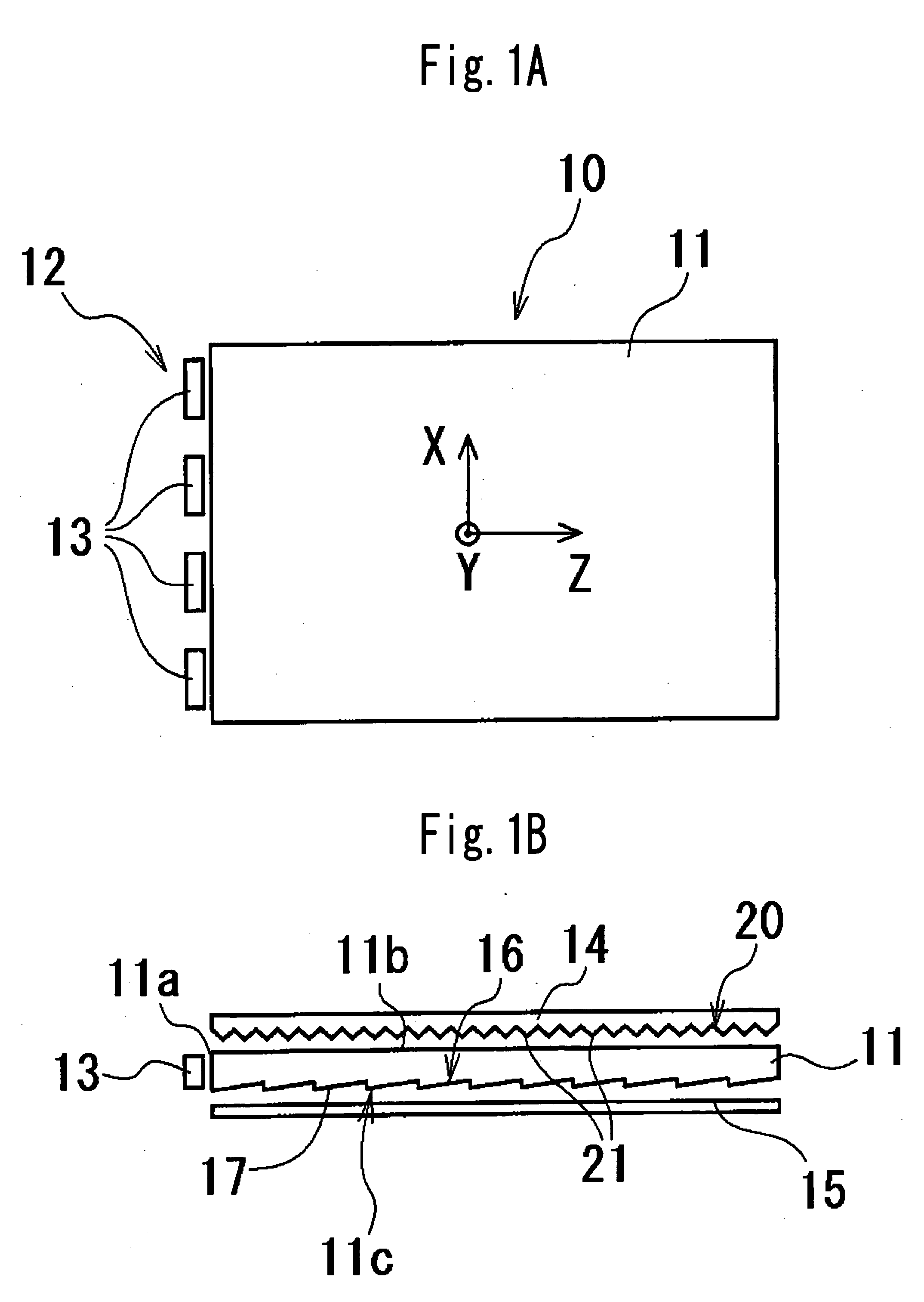
[0024] Referring to FIGS. 1A and 1B, a backlight system 10 in an embodiment of the present invention is shown. The backlight system 10 comprises a light-guiding plate 11 and a light source 12 to irradiate light to the light-guiding plate 11. The light source 12 comprises a plurality of light emitting diodes (LEDs) 13 in the shown embodiment, the LEDs 13 are disposed to face a light-entrance surface Ha formed on a side surface of the light-guiding plate 11 and arranged at intervals along the light-entrance surface 11a.

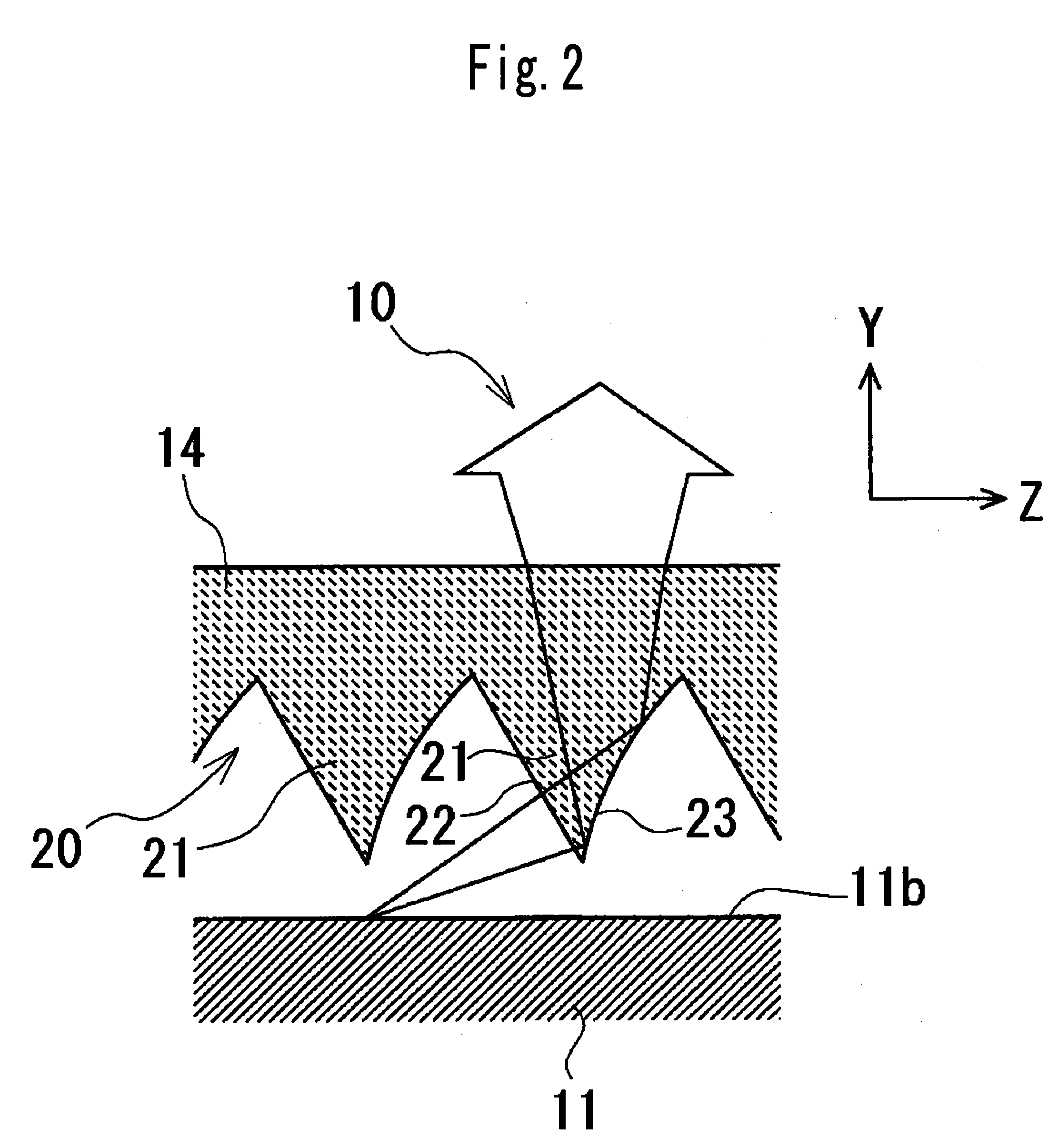
[0025] A prismatic sheet 14 is also disposed to face an upper surface 11b of the light-guiding plate 11 and adjacent to the upper surface 11b, and a reflecting sheet 15 is further disposed to face a lower surface 11c of the light-guiding plate 11 and adjacent to the lower surface 11c. Whether the prismatic sheet is disposed close to the upper surfa...


PUM

PropertyMeasurementUnit
brightnessaaaaaaaaaa
electric poweraaaaaaaaaa
reflectionaaaaaaaaaa

Abstract

A backlight system comprising a light-guiding plate having a light-entrance surface, an upper surface, and a lower surface, a light source disposed to face the light-entrance surface, a reflecting sheet disposed to face the lower surface of the light-guiding plate, a prismatic sheet disposed to face the upper surface of the light-guiding plate, and a micro-prismatic mechanism provided on the lower surface of the prismatic sheet, the micro-prismatic mechanism including a plurality of projection-like prismatic parts extending parallel to the light-entrance surface of the light-guiding plate and disposed at intervals in a generally perpendicular direction to the light-entrance surface, each prismatic part having a pair of prismatic surfaces, of each pair of prismatic surfaces, at least the prismatic surface on the side further from the light source forming into a curved surface.

Description

CROSS-REFERENCE TO THE RELATED APPLICATION [0001] The application claims the priority benefit of Japanese Patent Application No. 2004-45515, filed on Feb. 20, 2004, the entire descriptions of which are incorporated herein by reference. BACKGROUND OF THE INVENTION [0002] 1. Field of the Invention [0003] The present invention relates to a backlight system to illuminate a compact liquid crystal display from a back surface thereof, which is used in a mobile phone, a personal digital assistance (PDA) and the like. [0004] 2. Description of Related Art [0005] Recently, cost reduction, high-brightness, a wide viewing angle, a low-profile design, weight saving, low electric power consumption, and the like have become strict requirements for backlight systems to illuminate the compact liquid crystal displays used in mobiles, PDAs and the like. [0006] A light emitting diode (LED) having low electric power consumption and a low heat release value has been used as the light source of the backlig...

Claims


Application Information

Patent Timeline
Patent Type & Authority Applications(United States)
IPC IPC(8): F21S8/04G02F1/13357F21V5/02F21V7/04F21V8/00F21Y101/02G02B6/00G02F1/1335
CPCG02B6/0053G02B6/0038G02F1/1335
Inventor MIYASHITA, JUNJIWATANABE, KIYOKAZU
Owner CITIZEN ELECTRONICS CO LTD
Why Eureka
Try Eureka