
Radiographic apparatus and radiation detection signal processing method

a radiation detection and signal processing technology, applied in tomography, applications, instruments, etc., can solve the problems of reducing impairing the quality of x-ray sectional images, and achieve the effect of lowering the quality of radiation sectional images

Inactive Publication Date: 2005-08-25
SHIMADZU CORP
View PDF11 Cites 7 Cited by
  • Summary
  • Abstract
  • Description
  • Claims
  • Application Information

AI Technical Summary

Benefits of technology

[0014] This invention has been made having regard to the state of the art noted above, and its object is to provide a non-revolving type radiographic apparatus which can inhibit a lowering in quality of radiation sectional images caused by lag-behind parts included in radiation detection signals.
[0018] That is, the radiographic apparatus according to this invention can inhibit a lowering in quality of the radiation sectional images due to the lag-behind parts included in the radiation detection signals.
[0020] With this construction, the sectional image reconstructing device can reconstruct the radiation sectional images by a simple data processing, i.e. an integrating process to superimpose and compose transmission radiation images, utilizing the lag-free radiation detection signals obtained from the radiation detection signals of the transmission radiation images of the object detected from different radiographic angles.
[0022] This construction is effective to inhibit a lowering in quality of the radiation sectional images due to the lag-behind parts included in the radiation detection signals.
[0041] Where a flat panel X-ray detector is used, the time lag removing device eliminates the time lags in the radiation detection signals provided by the flat panel X-ray detector, and removes complicated detection distortions from output images.

Problems solved by technology

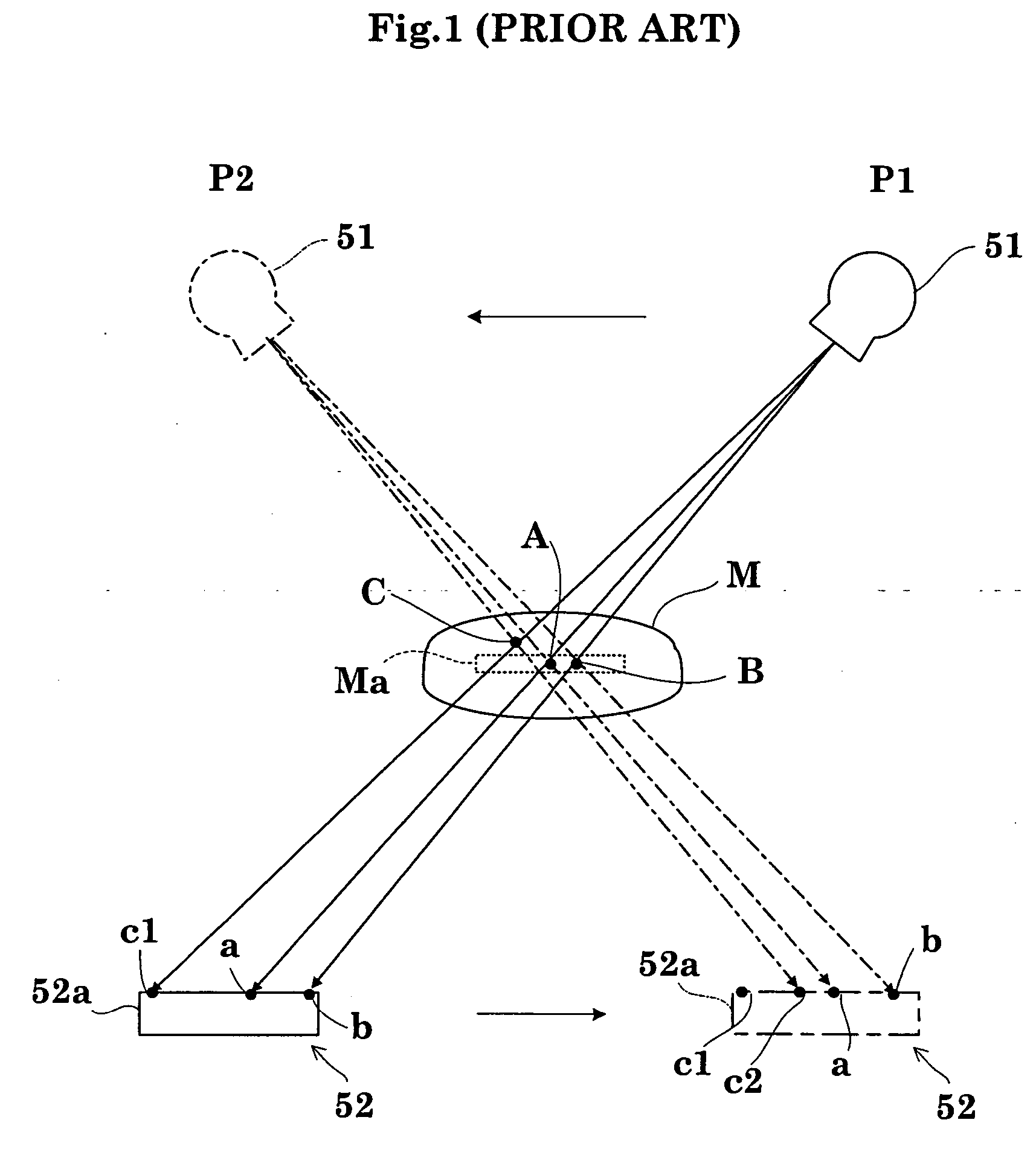
However, the conventional non-revolving type X-ray radiographic apparatus has a drawback of quality lowering of X-ray sectional images caused by lag-behind parts included in the X-ray detection signals.
This noise poses a problem of impairing the quality of X-ray sectional images.

Method used


Image

  • Radiographic apparatus and radiation detection signal processing method
  • Radiographic apparatus and radiation detection signal processing method
  • Radiographic apparatus and radiation detection signal processing method

Examples


Embodiment Construction

[0065] A preferred embodiment of this invention will be described in detail hereinafter with reference to the drawings.

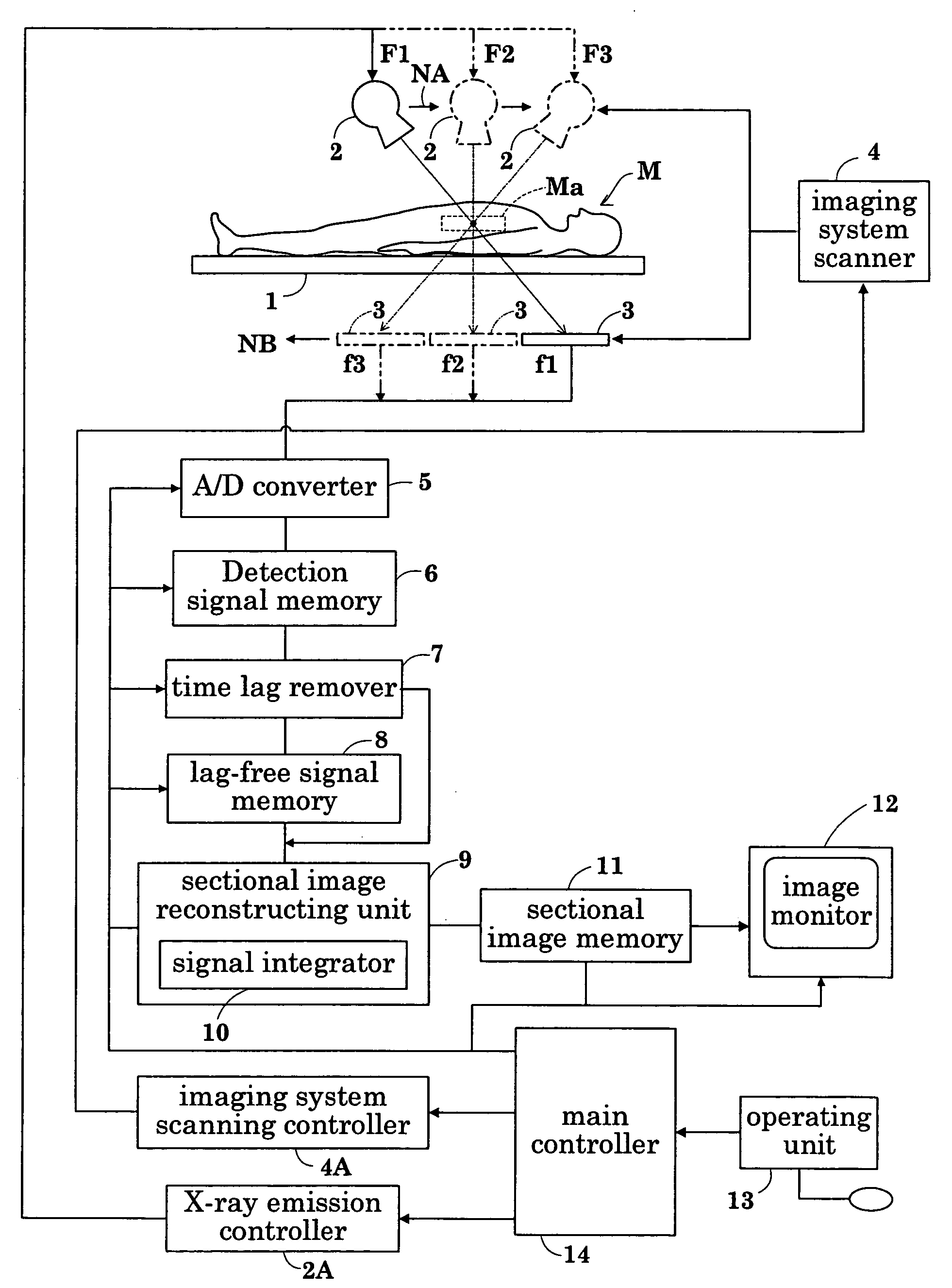
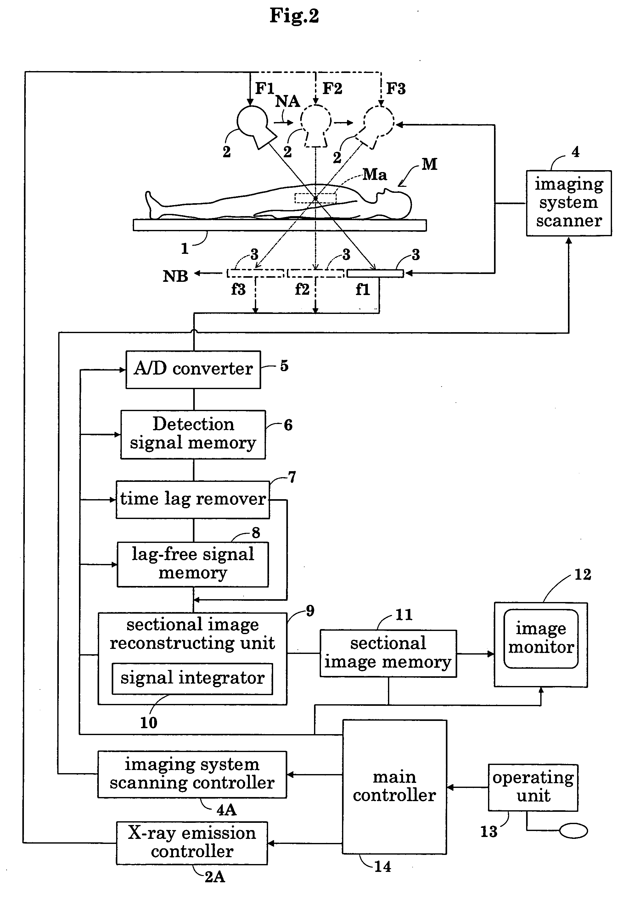
[0066]FIG. 2 is a block diagram showing an overall construction of an X-ray radiographic apparatus according to this invention.

[0067] As shown in FIG. 2, the X-ray radiographic apparatus includes a top board 1 for supporting a patient M to be radiographed, an X-ray tube 2 acting as a radiation emitting device for emitting a cone-shaped X-ray beam to the patient M on the top board 1, a flat panel X-ray detector 3 (hereinafter referred to as FPD as appropriate) acting as a planar radiation detecting device opposed to the X-ray tube 2 across the patient M for detecting transmission X-ray images of the patient M, and an imaging system scanner 4 acting as an imaging system scanning device for moving the X-ray tube 2 on one linear track NA of two linear tracks NA and NB acting as non-circular tracks opposed to each other across the patient M, and for moving the FPD 3 on...


PUM


Abstract

In a radiographic apparatus according to this invention, when an imaging system scan is performed, a imaging system scanner moves an X-ray tube, which emits a cone-shaped X-ray beam, on one linear track, and an FPD, which detects transmission X-ray images of an object under inspection, on the other linear track synchronously with movement of the X-ray tube. Thus, a non-revolving type imaging system scan is carried out. When an X-ray sectional image reconstruction is performed, a sectional image reconstructing unit reconstructs X-ray sectional image from X-ray detection signals of transmission X-ray images of the object detected by the FPD at different radiographic angles. At this time, a time lag remover uses lag-free X-ray detection signals with lag-behind parts removed from the X-ray detection signals. As a result, the lag-behind parts included in the X-ray detection signals, which would cause a lowering of image quality, are removed in advance of a reconstruction of X-ray sectional images.

Description

BACKGROUND OF THE INVENTION [0001] (1) Field of the Invention [0002] This invention has a radiation emitting device movable on one of two non-circular tracks opposed to each other across an object under inspection for emitting a cone-shaped beam, and a planar radiation image detecting device movable on the other track synchronously with movement of the radiation emitting device for detecting transmission X-ray images of the object. The invention relates to a non-revolving type radiographic apparatus for reconstructing radiation sectional images of the object based on radiation detection signals of transmission radiation images of the object detected from different radiographic angles by the radiation image detecting device in movement. More particularly, the invention relates to a technique for inhibiting a lowering in quality of radiation sectional images caused by lag-behind parts included in the radiation detection signals. [0003] (2) Description of the Related Art [0004] Convent...

Claims


Application Information

Patent Timeline
IPC IPC(8): A61B6/02A61B6/00A61B6/03G01N23/00G01T1/00G03B42/02G21K1/12H05G1/60
CPCA61B6/032A61B6/587A61B6/4441A61B6/03
Inventor OKAMURA, SHOICHI
Owner SHIMADZU CORP
Learn More