Golf ball with undercut dimples

a golf ball and dimple technology, applied in the field of golf balls with undercut dimples, can solve the problems of limiting the distance a golf ball can travel in several ways, non-traditional golf balls have been commercially unsuccessful, etc., and achieve the effect of increasing turbulen

Inactive Publication Date: 2005-08-25
TOPGOLF CALLAWAY BRANDS CORP
View PDF3 Cites 3 Cited by
  • Summary
  • Abstract
  • Description
  • Claims
  • Application Information

AI Technical Summary

Benefits of technology

[0033] The golf ball of the present invention increases the turbulence of air at the surface of the golf ball in order to reduce laminar flow resulting in less drag on the golf ball during flight, which results in greater distance when struck by a golf club.
[0035] When the face of a golf club strikes the golf ball, each of the impacted undercut area portions of the undercut dimples is momentarily compressed by the impact of the face of the golf club. Once the golf ball leaves the face, each of the undercut area portions springs back to a pre-impact configuration which allows the covered concavity area of each undercut dimple to increase turbulence at the surface of the golf ball.

Problems solved by technology

Many golf balls have been disclosed that break with this tradition, however, for the most part these non-traditional golf balls have been commercially unsuccessful.
These specifications limit how far a struck golf ball will travel in several ways.

Method used


Image

  • Golf ball with undercut dimples
  • Golf ball with undercut dimples
  • Golf ball with undercut dimples

Examples


Embodiment Construction

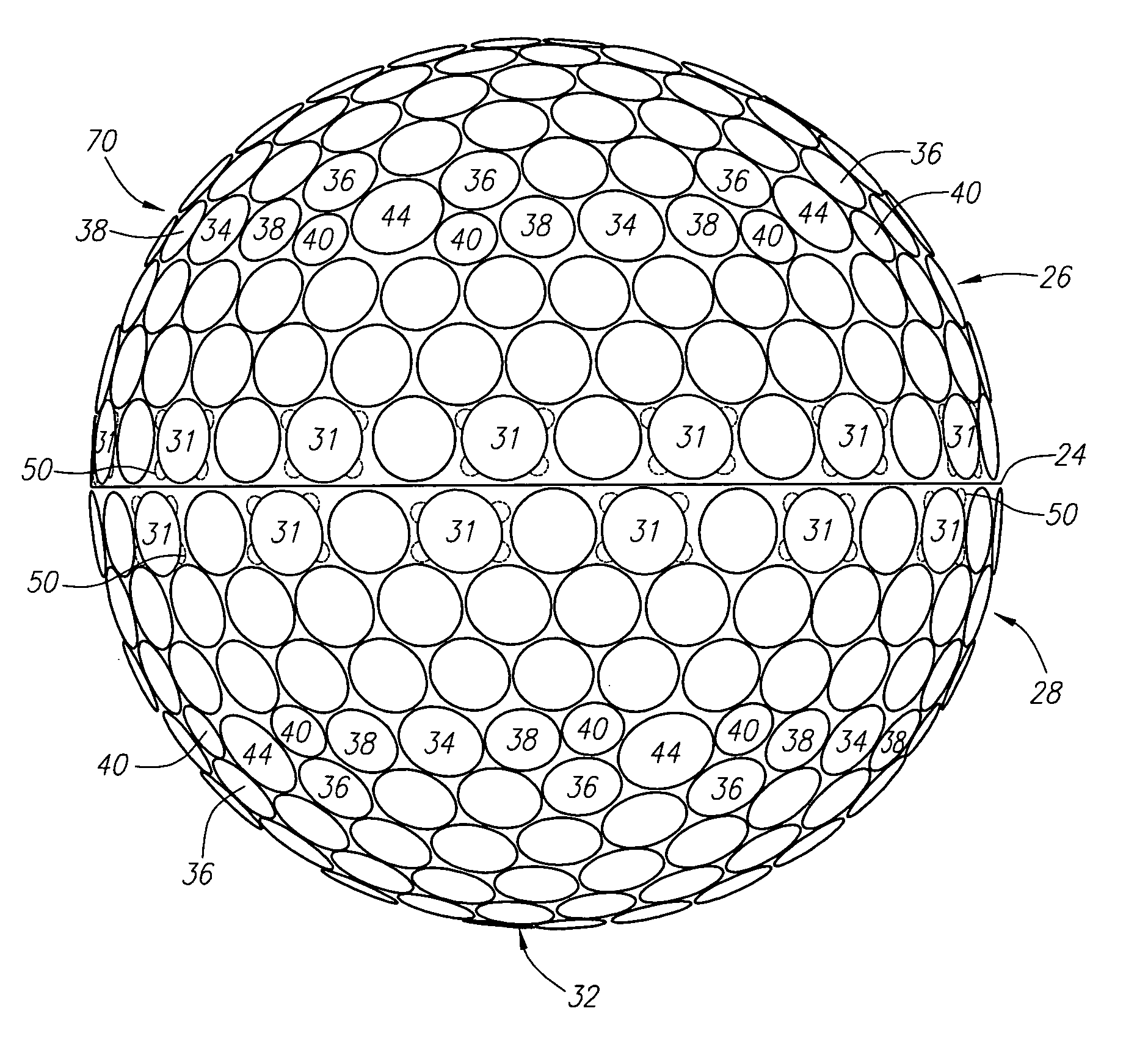
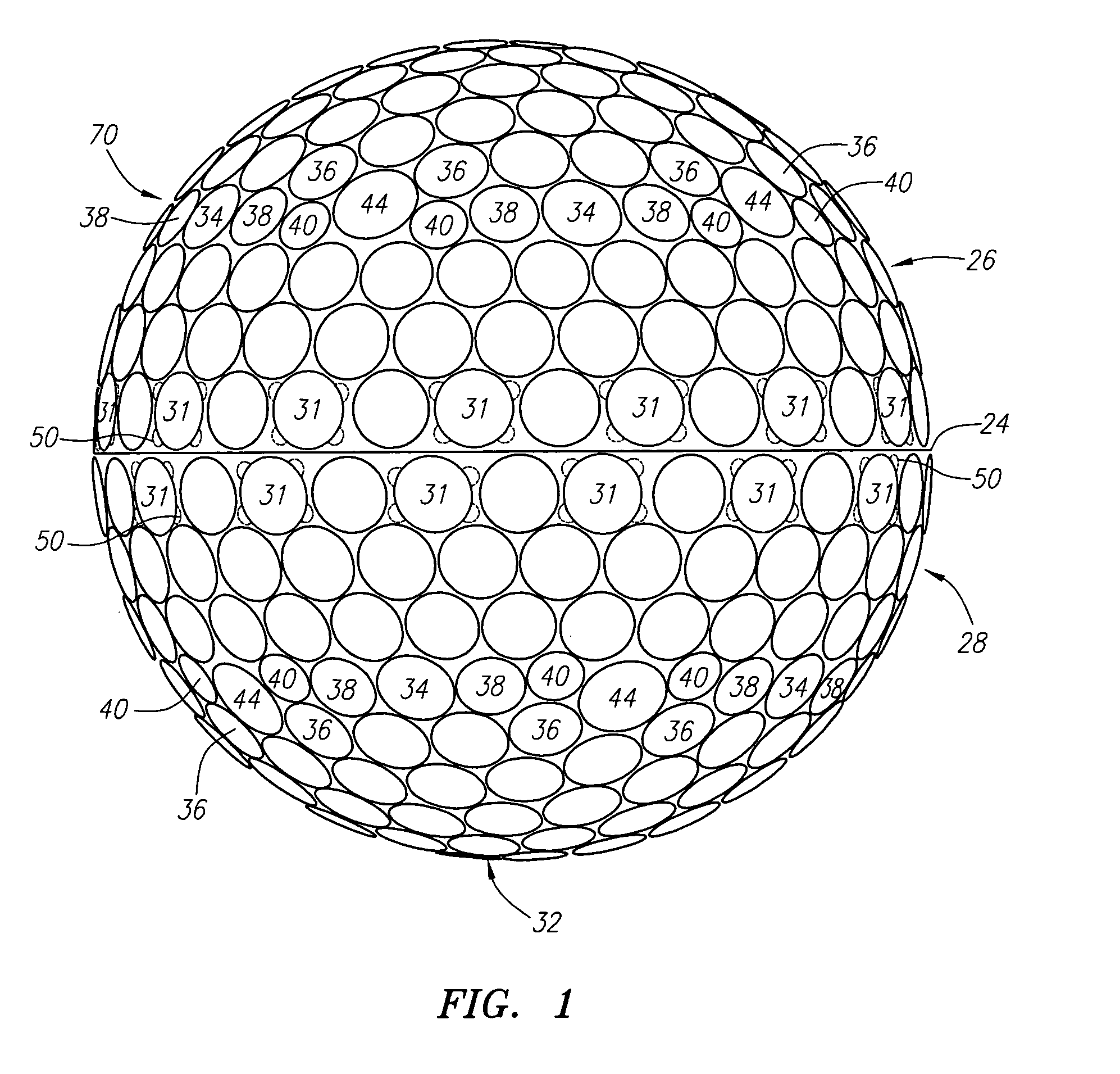
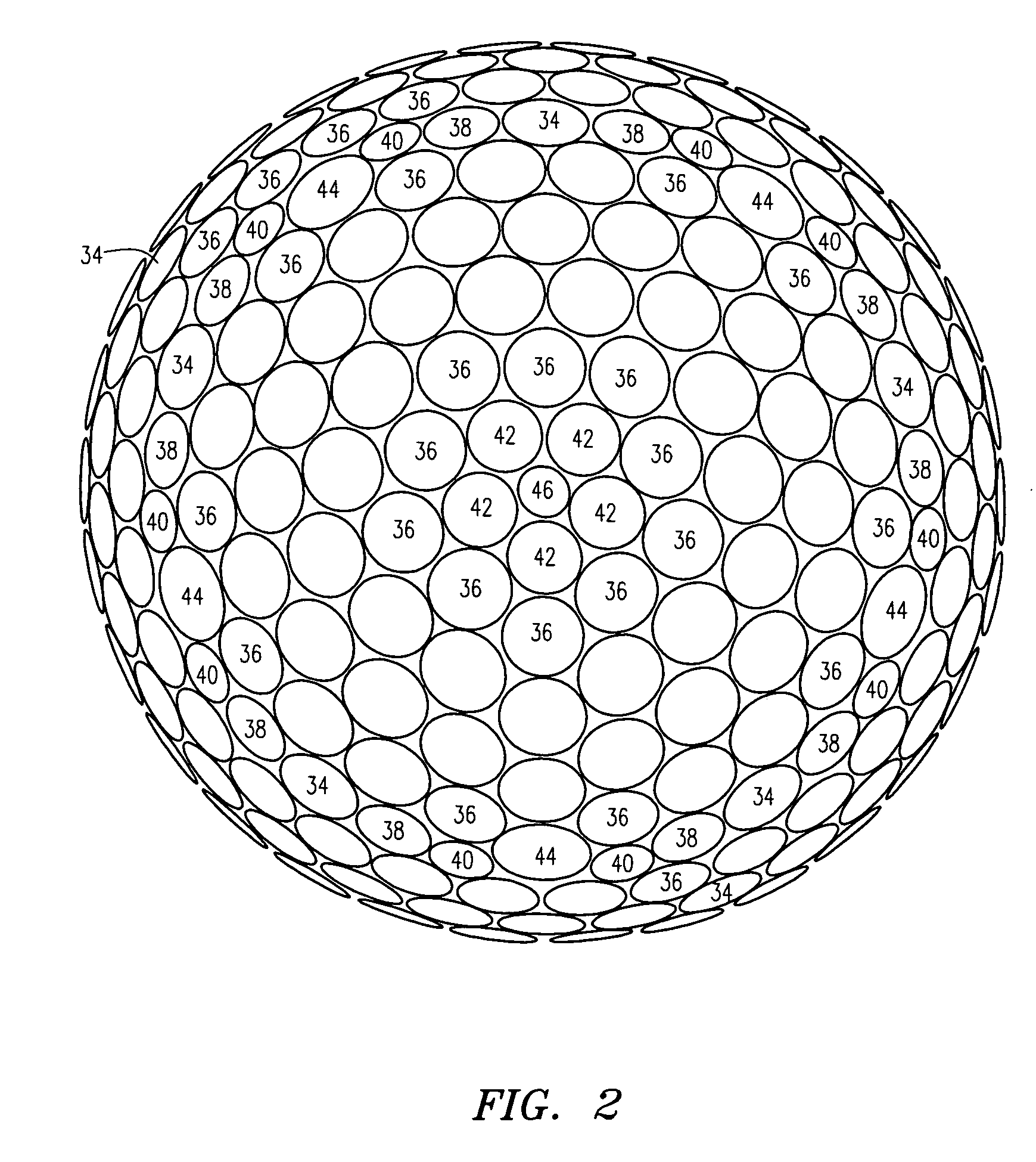
[0051] As shown in FIGS. 1-5, a golf ball is generally designated 20. The golf ball 20 may be a two-piece golf ball, a three-piece golf ball, or a greater multi-layer golf ball. The construction of the golf ball is discussed in greater detail below.

[0052] As shown in FIGS. 1-4, the golf ball 20 has a surface 22. The golf ball 20 preferably has an equator 24 dividing the golf ball 20 into a first hemisphere 26 and a second hemisphere 28. A first pole 30 of the golf ball 20 is located ninety degrees along a longitudinal arc from the equator 24 in the first hemisphere 26. A second pole 32 of the golf ball 20 is located ninety degrees along a longitudinal arc from the equator 24 in the second hemisphere 28.

[0053] On the surface 22 of the golf ball 20 are a plurality of undercut dimples 31, a plurality of standard dimples 33 and land area 35. Each of the plurality of undercut dimples 31 has at least one undercut area portion 50. The undercut area portion 50 extends from under the land ...


PUM


Abstract

A golf ball (20) having a plurality of standard dimples (33) and a plurality of undercut dimples (31) is disclosed herein. Each of the plurality of undercut dimples (31) has at least one undercut area portion (50) that extends into a portion of a concavity (55) of the undercut dimple (31). A covered region (70) defined by the undercut area portion (50) generates eddy currents during the flight of the golf ball (20) which creates greater turbulence at the surface (22) of the golf ball (20) allowing for greater distance.

Description

CROSS REFERENCES TO RELATED APPLICATIONS [0001] This application is a continuation-in-part application of U.S. patent application Ser. No. 10 / 900,692, filed Jul. 27, 2004, which is a continuation application of U.S. patent application Ser. No. 09 / 730,867, filed Dec. 6, 2000, now U.S. Pat. No. 6,767,295.STATEMENT REGARDING FEDERALLY SPONSORED RESEARCH OR DEVELOPMENT [0002] Not Applicable BACKGROUND OF THE INVENTION [0003] 1. Field of the Invention [0004] The present invention relates to an aerodynamic surface geometry for a golf ball. More specifically, the present invention relates to a golf ball having a plurality of undercut dimples. [0005] 2. Description of the Related Art [0006] Golfers realized perhaps as early as the 1800's that golf balls with indented surfaces flew better than those with smooth surfaces. Hand-hammered gutta-percha golf balls could be purchased at least by the 1860's, and golf balls with brambles (bumps rather than dents) were in style from the late 1800's to...

Claims


Application Information

Patent Timeline
Patent Type & Authority Applications(United States)
IPC IPC(8): A63B37/00
CPCA63B37/0004A63B37/0006A63B37/0018A63B37/0021A63B37/0026A63B37/0033A63B37/0074A63B37/0075A63B37/0076A63B37/0024A63B37/00065
Inventor KENNEDY, THOMAS J. III
Owner TOPGOLF CALLAWAY BRANDS CORP
Why Eureka
Try Eureka