[0006] Hereupon, it is an object of the invention to provide a flow velocity measuring device capable of conducting a fluid to a sensor element after removal of dust and dirt contained in the fluid to enable accurately measuring the flow velocity of the fluid even when the fluid is low in flow velocity and the device is mounted in any direction.
[0008] With this construction, when the flow velocity measuring device is placed in a fluid flow, a fluid is introduced from the introduction passage to the inner space by the fluid flow and the fluid flows along the curved wall surface of the internal space to be discharged from the
discharge passage. At this time, dust and dirt contained in the fluid is locally distributed near the wall surface trying to go straight according to a law of
inertia, so that a pure fluid with less dust and dirt is obtained in a region distant from the wall surface of the internal space. The pure fluid can be taken out from the internal space without disturbing a flow of the fluid along the wall surface from the branch passage provided at substantially right angle to a direction along the introduction passage, the discharge passage, and the wall surface connecting between the both passages. Since the flow velocity of the pure fluid is dependent upon the flow velocity of a fluid outside the flow velocity measuring device, the flow velocity of a fluid outside can be found by measuring the flow velocity of the pure fluid with the sensor element. Also, since
inertia of dust and dirt can be caused by largely bending a direction, in which a fluid flows along the wall surface, to act, dust and dirt is separated even when the flow velocity of the fluid is small, thus enabling measurement of the flow velocity.
[0010] In this manner, when the internal spaces are connected together in series, it is possible to surely remove dust and dirt from a fluid fed to the sensor element. Even with the internal spaces connected together in parallel, the internal spaces are individually made small provided that the flow velocities in the respective internal spaces are made equal to the flow velocity in the case of the internal space being single, and so a
radius of curvature becomes small, so that the effect of separation of dust and dirt owing to inertia is heightened. Also, even when one of the internal spaces or any flow passage connected to the internal space is plugged, a path extending through the other internal spaces functions, so that measurement of flow velocity can be done by adjustment of sensitivity. Also, depending upon the positional relationship between the branch passages, through which a pure air is taken out from the internal spaces, and the discharge passages, through which dust and dirt are carried out, in particular, when the discharge passages are positioned above openings of the branch passages, a part of dust and dirt falls in some cases into the fluid, which is separated by
gravitation from flows leading to the discharge passages and taken out into the branch passages. When the plurality of internal spaces are connected with directions of the branch passages being changed, and / or arranged with directions of the branch passages being changed, preferably the branch passages in directions different by 90° or more, more preferably 180°, the discharge passage is not positioned above the opening of the branch passage in at least one of the internal spaces, so that it is possible to optimally perform separation of dust and dirt.
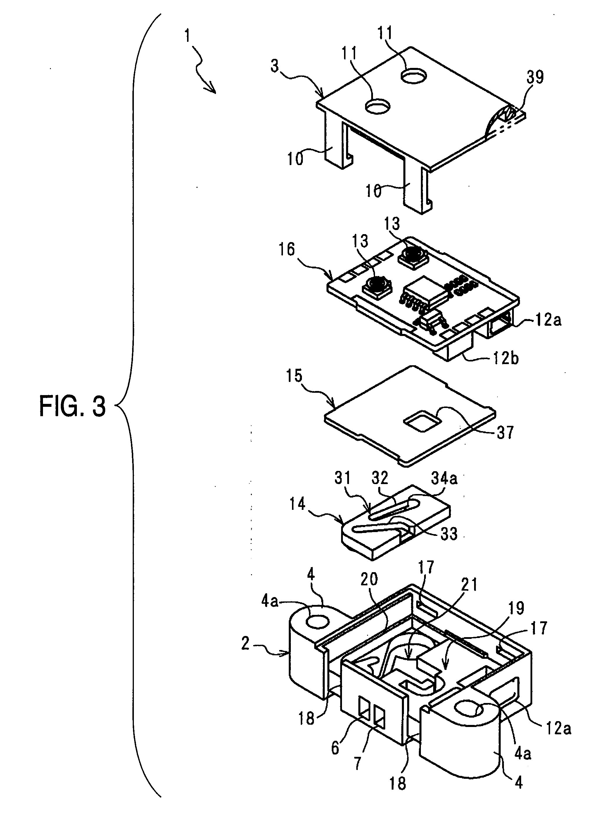
[0016] With this construction, the groove provided on the intermediate plate is closed by the circuit substrate provided with an
electronic circuit for the sensor element to configure the second layer flow passage, so that the number of parts is decreased and the construction is made simple. Also, the construction is made simple by making the first layer substrate integral with that structure, which accommodates therein the whole device.
[0022] By projecting the opening of the branch passage into the internal space, dust and dirt in a fluid is hard to enter into the through-hole by
gravitation even when the flow velocity measuring device is mounted with the intermediate plate disposed under. Also, by making the internal spaces cylindrical-shaped, flows of a fluid describe a circle, so that separation of dust and dirt is efficient.
[0023] As described above, for a fluid at low flow velocity and even when the device is mounted in any direction, it is possible according to the invention to remove dust and dirt in a fluid to conduct the fluid to a sensor element to accurately measure the flow velocity of the fluid over a long term.

