Check patentability & draft patents in minutes with Patsnap Eureka AI!

Portable-terminal holder and radio communication system

a terminal holder and radio communication technology, applied in the field of terminal holder and radio communication system, can solve the problems of reducing working efficiency, needing to recharge, and wasting the battery of scanner units,

Active Publication Date: 2005-09-01
DENSO WAVE INC
View PDF10 Cites 12 Cited by
  • Summary
  • Abstract
  • Description
  • Claims
  • Application Information

AI Technical Summary

Benefits of technology

[0031] With this structure, if the user assigns a local ID to the first radio terminal operating as a target terminal, it becomes possible for the user to save the trouble of setting an absolute ID of the first radio terminal in the second radio terminal operating as a calling terminal.
[0043] With this structure, if the user assigns a local ID to each of the first and second radio terminals, it becomes possible for the user to save the trouble of setting the absolute 10 of the first or second radio terminal operating as a target terminal in the first or second radio terminal operating as a calling terminal.

Problems solved by technology

However, in a case where the user uses the scanner unit for many hours, it frequently occurs that the battery of the scanner unit becomes exhausted, and needs to be recharged.
If the workplace is distant from the host computer, the user has to bring the scanner unit to the holder placed in a location distant from the workplace, because the length of the cable connecting the holder and the host computer is generally limited to 1 m-3 m. This lowers the working efficiency, especially when the user uses only one scanner unit.
This problem arises also in holders for cellular phones or PDAs.
However, it is very troublesome for the user to handle the 48-bit Bluetooth addresses, especially in a radio communication system constituted by a host computer not provided with a display device such as an LCD, and peripheral devices (input-output device, data storage, and the like) connected to the host computer through a radio communication network, because the above described technique disclosed in Japanese Patent Application Laid-open No. 2001-144767 cannot be used in such a radio communication system.
Moreover, even if the host computer is provided with a function of displaying detected communication terminals on its display device to enable selecting, from among them, a communication target, it is not easy for the user to remember their absolute IDs.

Method used


Image

  • Portable-terminal holder and radio communication system
  • Portable-terminal holder and radio communication system
  • Portable-terminal holder and radio communication system

Examples


first embodiment

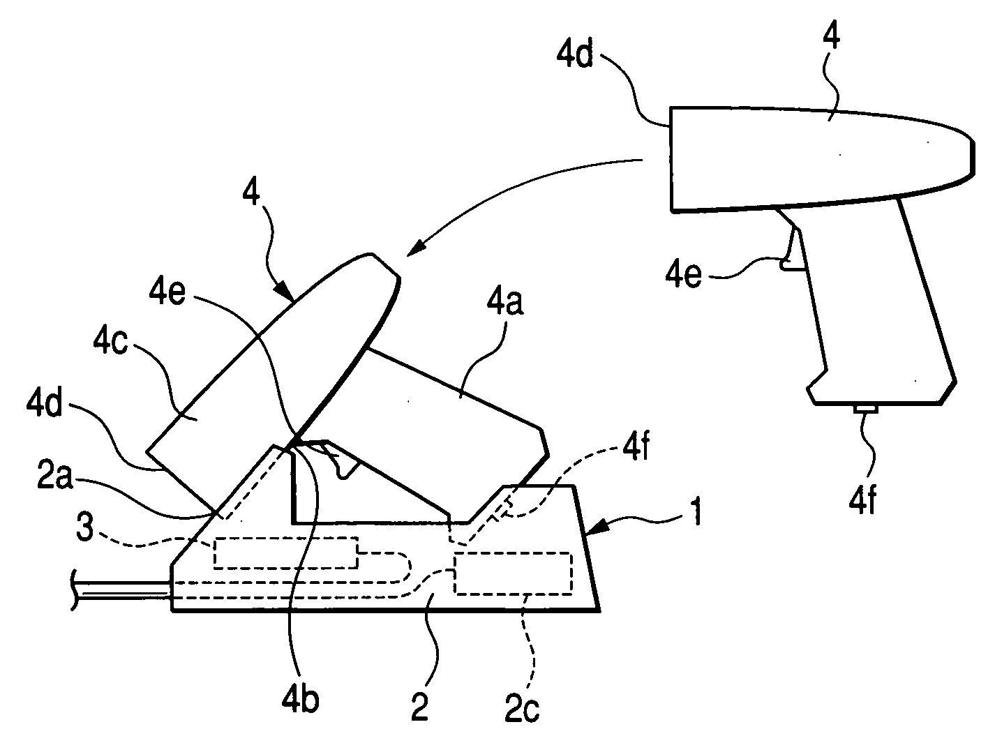
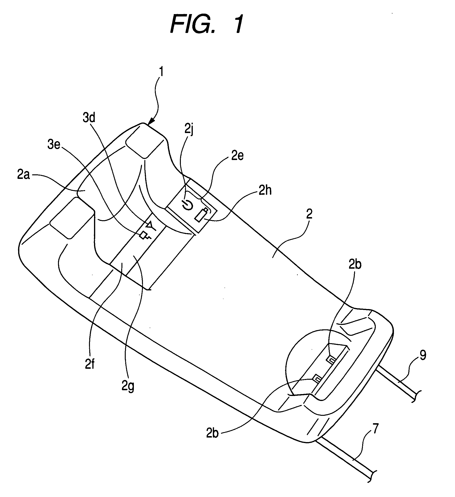
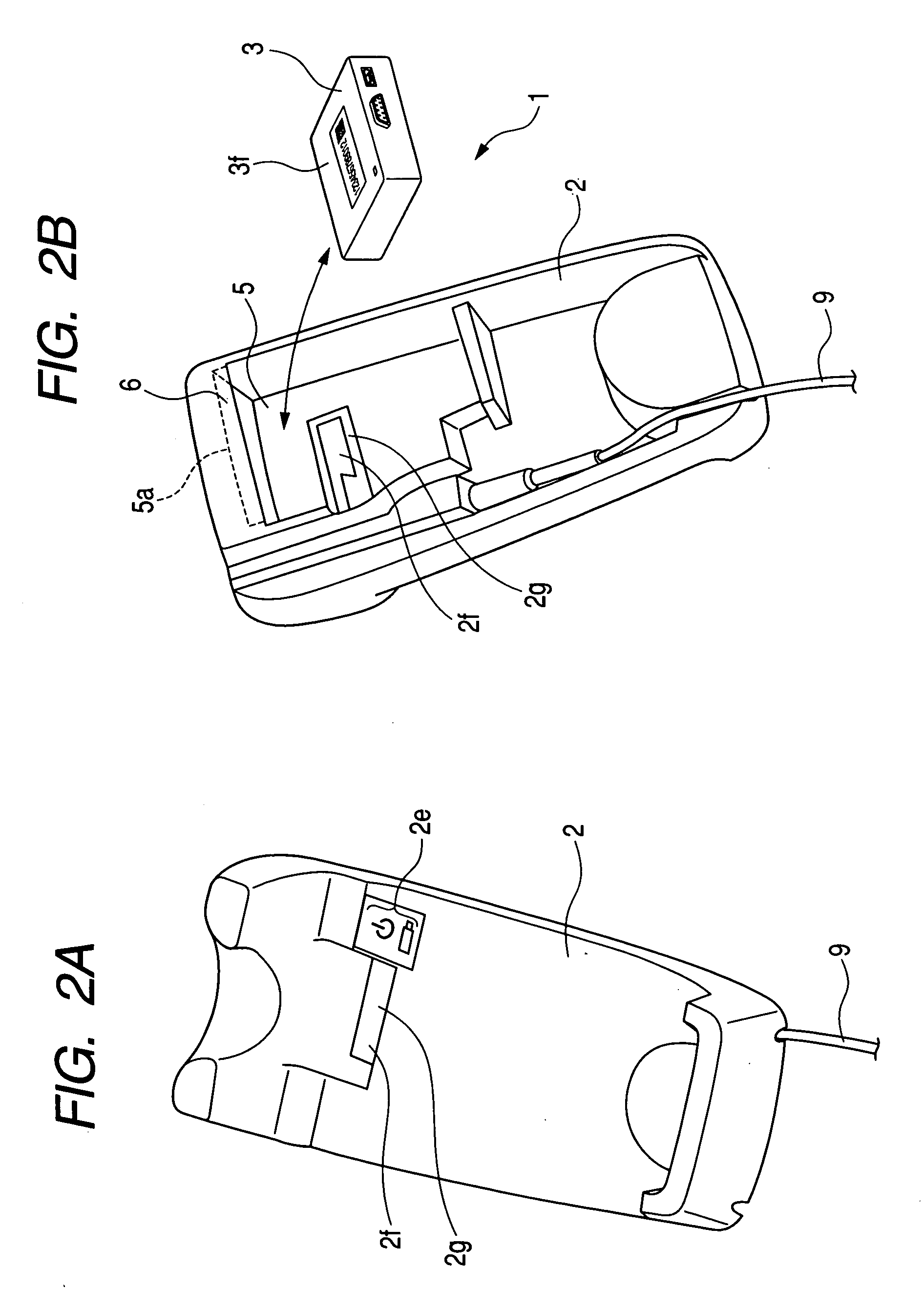
[0081] A portable-terminal holder according to an embodiment of the invention has a base for receiving thereon a portable terminal and a communication module. FIG. 1 is a diagram showing the portable-terminal holder 1 (referred to as simply holder 1 hereinafter) fitted with the communication module 3 when viewed from above. FIG. 2A is a diagram showing the holder 1 separated from the communication module 3 when viewed from above, and FIG. 2B is a diagram showing the holder 1 separated from the communication module 3 when viewed from below.

[0082] As shown in FIG. 2B, the communication module 3 has a box shape, and the base 2 has a hollow portion 5 at its bottom for housing therein the communication module 3. The base 2 has also a protruding plate 6 at its bottom inwardly protruding from an outer end 5a of the hollow portion 5 so as to cover a part of the hollow portion 5. This protruding plate 6 enables the communication module 3 to be snapped into the hollow portion 5.

[0083]FIGS. ...

second embodiment

[0105]FIG. 9 is a diagram showing a schematic structure of a radio communication system S used for reading information codes according to a second embodiment of the invention. As shown in this figure, the radio communication system S includes a host computer P, a plurality of portable scanner units B1 to B6 (collectively represented by B hereinafter) having the same structure, and one or more relay units A1 to A3 (collectively represented by A hereinafter) having the same structure. The scanner units B and the relay units A constitute a local area network N.

[0106] The relay units A are cable-connected to the host computer P through a hub H such as a USB (Universal Serial Bus). The scanner units B are radio-connected to the relay units A which serve also as holders of the scanner units A.

[0107]FIG. 10A is a block diagram showing an electrical configuration of the scanner units B. The scanner units B include a control circuit 111, a lighting device drive circuit 112, a lighting devi...

third embodiment

[0136]FIG. 16 is a sequence diagram explaining an operation of the radio communication system according to a third embodiment of the invention. The third embodiment is different from the second embodiment in that the third embodiment uses an auxiliary local ID for establishing communication in an emergency mode or a test mode, and that the scanner units has a receiving-only mode.

[0137] The auxiliary local ID is prestored in the nonvolatile memory of the memory device 110 or 130. The auxiliary local ID is used instead of the regular local ID explained in the second embodiment when the radio communication system is in fault condition, or when fault diagnosis is performed, or when the radio communication system is in an auxiliary mode (test mode or emergency mode). The auxiliary local ID is assigned in common to all the relay units A1 to A3 and the scanner units B1 to B6 constituting the local network N. The auxiliary local ID may be used for validating received local IDs when the rad...


PUM


Abstract

A portable-terminal holder for holding a portable terminal that has a rechargeable battery and a first radio communication device is constituted by a base and c communication module. The base has a portion on which the portable terminal is placed, and a charging device for charging the rechargeable battery of the portable terminal while said portable terminal is placed on the portion. The communication module has a second radio communication device communicating with the first radio communication device for wireless data transmission between the portable terminal and the communication module, and a cable communication device communicating with an external host computer for cable data transmission between the host computer and the communication module. The communication module is configured to be detachable from the base.

Description

CROSS-REFERENCE TO RELATED APPLICATION [0001] This application is related to Japanese Patent Applications No. 2004-53788 filed on Feb. 27, 2004, and No. 2004-53789 filed on Feb. 27, 2004, the contents of which are hereby incorporated by reference. BACKGROUND OF THE INVENTION [0002] 1. Field of the Invention [0003] The present invention relates to a portable-terminal holder being able to charge a portable terminal and relay data between the portable terminal and a host computer. [0004] The present invention also relates to a radio communication system including a plurality of radio communication terminals each of which has an absolute ID and a capability of performing radio communication with other radio communication terminals in conformity with a specific radio communication standard. [0005] 2. Description of Related Art [0006] Japanese Patent Application Laid-open No, 2002-334299 discloses that a rechargeable battery of a scanner unit functioning as a portable terminal is charged ...

Claims


Application Information

Patent Timeline
Patent Type & Authority Applications(United States)
IPC IPC(8): G06K7/00G06K7/10
CPCG06K7/10881G06K7/109G06K7/10821G06K7/10475G06K17/0022
Inventor KUROBE, TAKAHIRONAGAI, YOSHIKI
Owner DENSO WAVE INC
Features
  • R&D
  • Intellectual Property
  • Life Sciences
  • Materials
  • Tech Scout
  • Unparalleled Data Quality
  • Higher Quality Content
  • 60% Fewer Hallucinations
Learn More