
Cable organizer

a technology of cable organizer and cable, which is applied in the field of cable organizer, can solve the problems of burdensome threading of cables through such openings and channels, matched and exceeded growth in the number of such computing devices, and high price of desks

Inactive Publication Date: 2005-09-01
DEGUEVARA ORLANDO
View PDF47 Cites 89 Cited by
  • Summary
  • Abstract
  • Description
  • Claims
  • Application Information

AI Technical Summary

Benefits of technology

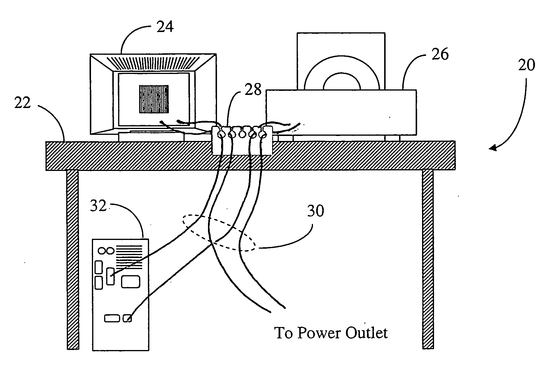
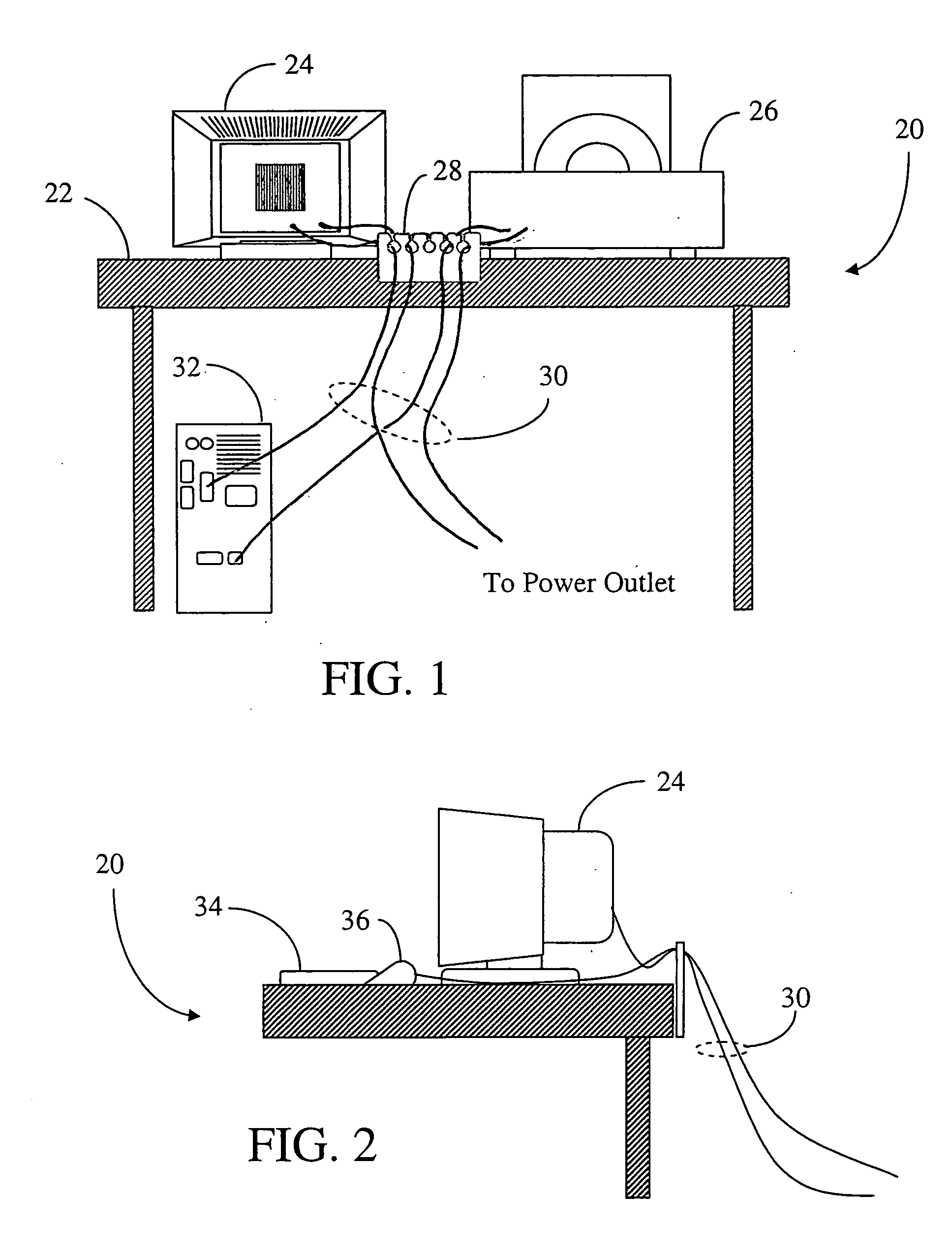
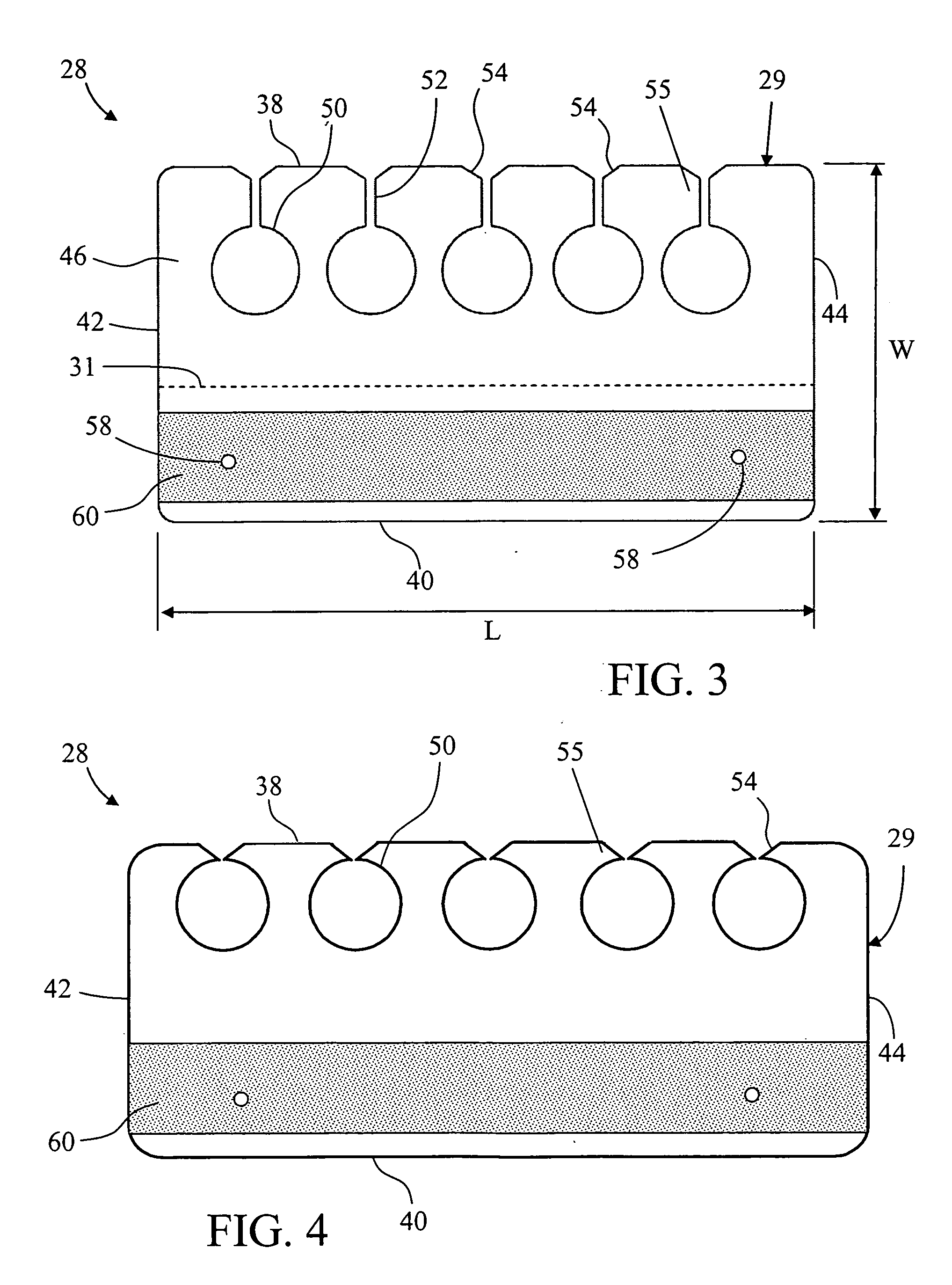
[0010] In its simplest embodiment, the cable organizer is substantially planar. However, the cable organizer may include a hinge, such as a living hinge, to allow the cable organizer to fold along a predetermined line, thus facilitating fastening the cable organizer to such broad objects as a wall, which fastening would otherwise inhibit passing a cable through the opening or slots of the organizer. In yet another embodiment, the cable organizer can be manufactured and rolled or coiled for later cutting into convenient lengths.
[0011] The cable organizer according to the present invention is relatively thin and essentially 2-dimensional, having a thickness typically less than about 2 mm. The thickness of the adhesive strip is insignificant compared to the thickness of the overall cable organizer, making the cable organizer a substantially uniform thickness.

Problems solved by technology

Unfortunately, the growth in the number of such computing devices has been matched and exceeded by the amount of peripheral equipment that is or can be commonly attached to the processing unit / enclosure.
In spite of these advancements, such desks are expensive, and threading the cables through such openings and channels is burdensome, particularly if equipment must be frequently moved and / or re-configured.
When the cables connecting the peripheral devices to the processor enclosure are disconnected, they typically fall to the floor.
This can prove to be burdensome in an environment where such changes occur often.

Method used


Image

  • Cable organizer
  • Cable organizer
  • Cable organizer

Examples


Embodiment Construction

[0024] In the following, preferred embodiments of the cable organizer in accordance with the present invention will be explained in detail with reference to the drawings. In the explanation of the drawings, constituents identical to each other will be referred to with numerals or letters identical to each other, without repeating their overlapping descriptions. Also, ratios of sizes in the drawings do not always coincide with those explained.

[0025] Although various tables, desks, cabinets and other furniture pieces have been designed to accommodate computers and related peripheral equipment, such furniture pieces do not all provide a means for organizing and retaining the data cables and power cables associated with the computer equipment. In addition, such specialized pieces of furniture tend to be expensive compared to their non-computer counterparts, making their use financially burdensome, particularly in environments where a large number of computers are deployed. Thus, often ...


PUM


Abstract

Disclosed is a cable organizer for organizing and retaining cables including a thin sheet of flexible material having at least one opening adjacent an edge of the material. The cable organizer is further comprised of openings arranged along an edge of the cable organizer and in communication with the edge to allow the passage of a cable into the opening. The openings are sized to to prevent the passage of a cable connector such that a cable connector located on the end of the cable is unable to pass through the opening. Thus, the cable end may be retained by the cable organizer in a convenient position for future re-connection. The cable organizer may also provided with an adhesive strip for adhering the cable organizer to an object.

Description

[0001] This application claims the benefit of priority under 35 U.S.C. § 119(e) of U.S. application Ser. No. 10 / 621,876 filed Jul. 16, 2003, the content of which is relied upon and incorporated herein by reference in its entirety.BACKGROUND OF THE INVENTION [0002] 1. Field of the Invention [0003] The invention relates to a cable organizer for organizing and holding electrical power and / or data cables. [0004] 2. Technical Background [0005] Computers are ubiquitous. Having moved from room-sized enclosures to hand-held devices and smaller, there is virtually not an aspect of daily life that is not touched by computers in one way or another. The markets for computing equipment, and in particular so-called personal, or desktop, computers (PCs) and more portable laptop computers have undergone significant growth over the last decade. Both desktop and laptop computers can be found in home, office and educational environments. Unfortunately, the growth in the number of such computing device...

Claims


Application Information

Patent Timeline
IPC IPC(8): H02G3/30
CPCH02G3/305
Inventor DEGUEVARA, ORLANDO
Owner DEGUEVARA ORLANDO
Learn More