Pallet jack stop

a pallet jack and stop technology, applied in the direction of machine supports, braking systems, furniture parts, etc., can solve the problems of heavy pallet jacks, extensive property damage, serious injuries to warehouse workers and other personnel, etc., and achieve the effect of reducing the weight of the device and the amount of material required

Inactive Publication Date: 2005-09-01
FENYVES MARVIN +1
View PDF8 Cites 5 Cited by
  • Summary
  • Abstract
  • Description
  • Claims
  • Application Information

AI Technical Summary

Benefits of technology

[0017] The pallet jack stop is a compact, portable, sturdy cradle for restricting the movement of the pivot wheel(s) of a warehouse style pallet jack, thus restricting the movement of the pallet jack itself when not in use. The cradle is generally rectangular in shape, having a closed bottom with a short sloping ramp or bevel on one side. In a preferred embodiment, a rectangular carrying handle is disposed on the side of the pallet jack stop opposite the ramp, although the handle may be positioned elsewhere on the pallet jack stop or eliminated entirely. Slots or recesses may be defined in the bottom surface of the device to reduce the weight of the device and the amount of material required for its manufacture. The cradle is made of a molded or extruded dense rubber, or other suitable sturdy resilient material.
[0018] The pallet jack stop is sturdy, easily portable and compact. It can easily be carried and used with one hand by adults who are physically fit enough to engage in warehouse and freight handling work. When not needed, the pallet jack stop can be quickly stored out of the way of warehouse traffic, safely placed on top of palletized materials or placed on a hook or holder provided on the pallet jack. The pallet jack stop is made of material of sufficient strength and elasticity as to allow it to repeatedly bear the weight of standard unloaded and loaded pallet jacks under the entire range of environmental conditions found in warehouses and cargo carriers, to include standard allowances for impact loading with safety factors. The pallet jack stop is made of materials that comply with the normally accepted criteria for combustibility, smoke generation and environmental protection.
[0019] Accordingly, it is a principal object of the invention to provide a pallet jack stop for immobilizing the pivot wheel of a pallet jack, so that a loaded or unloaded pallet jack will not move when the device is used on a sloped or moving surface.

Problems solved by technology

These metal structures and pump mechanisms may cause the pallet jack to weigh several hundred pounds, even when unloaded.
Whether unloaded or loaded, the heavy metal pallet jacks tend to move along their bottom rollers and pivot wheels if the surface where the jack was placed becomes unstable, as in the back of a freight car or cargo carrying vehicle.
If adequate precautions are not taken to restrain the movement of an unused pallet jack, its uncontrolled movements may cause extensive property damage.
These uncontrolled movements of the pallet jacks could also seriously injure warehouse workers and other personnel.
Restricting the movement of the pivot wheel at the structural base of the jack generally immobilizes the entire device, even when the supporting surface is unstable or sloping.
The problem of restricting the movement of heavy items with roller, wheeled feet or bases is not limited to the problem of pallet jacks.
Larger pieces of home furnishings, (i.e. pianos, beds, sofas, etc.) automobiles, and motorcycles present very similar problems to warehouse persons and freight carriers.
The problem with devices having long heavy ramps is that often their size and weight can create additional material handling difficulties.
Wheel cradles of various depths will often adequately restrain the wheel(s) of a heavy item to prevent rolling, but may not adequately address the problem of resistance to the sliding movement of a fixed wheeled support.
Such ramps are not suited to the task of restraining a pallet jack from movement because while the purpose of the vehicle ramps is to raise a vehicle for access below the vehicle, it is not desirable to elevate a pallet jack more than a minimum necessary to immobilize the pallet jack.

Method used


Image

  • Pallet jack stop
  • Pallet jack stop
  • Pallet jack stop

Examples


Embodiment Construction

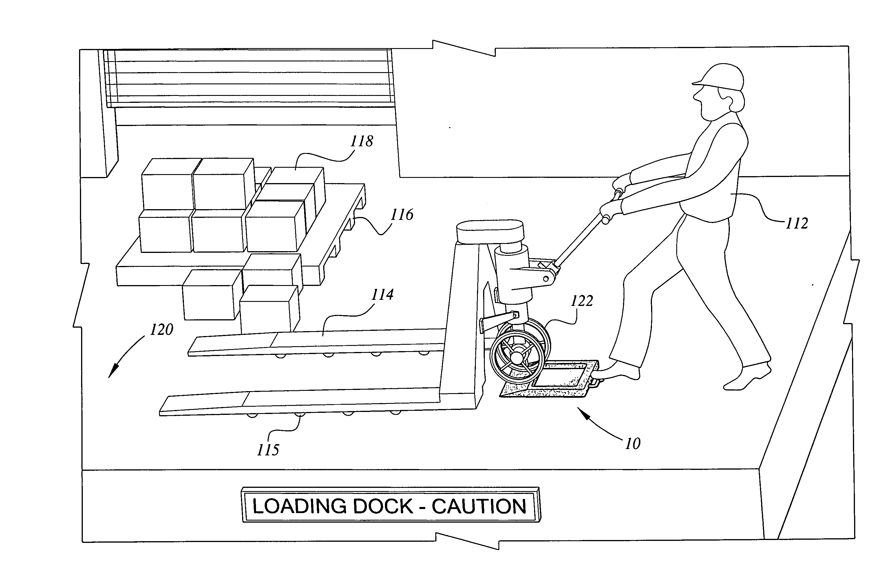
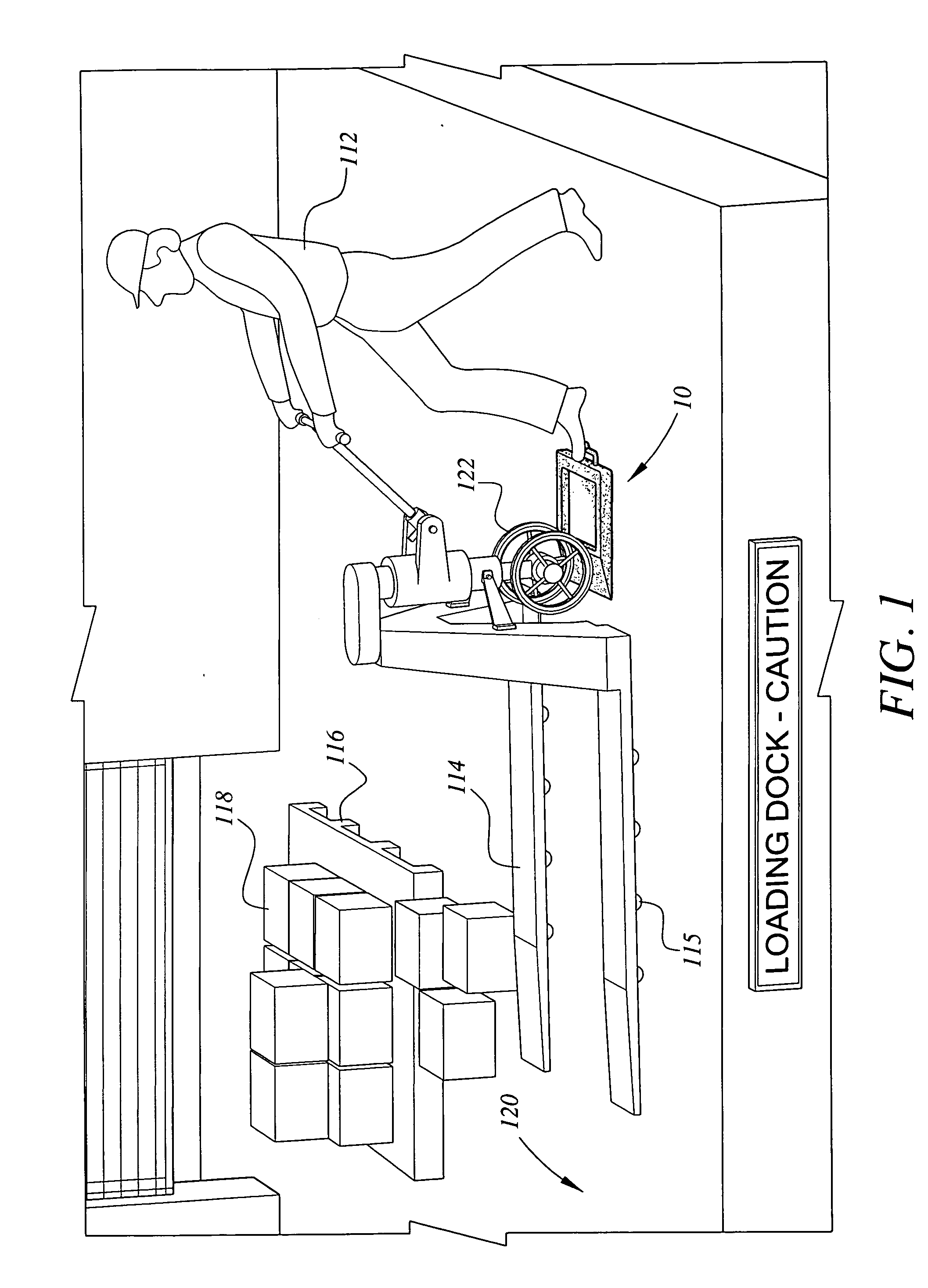
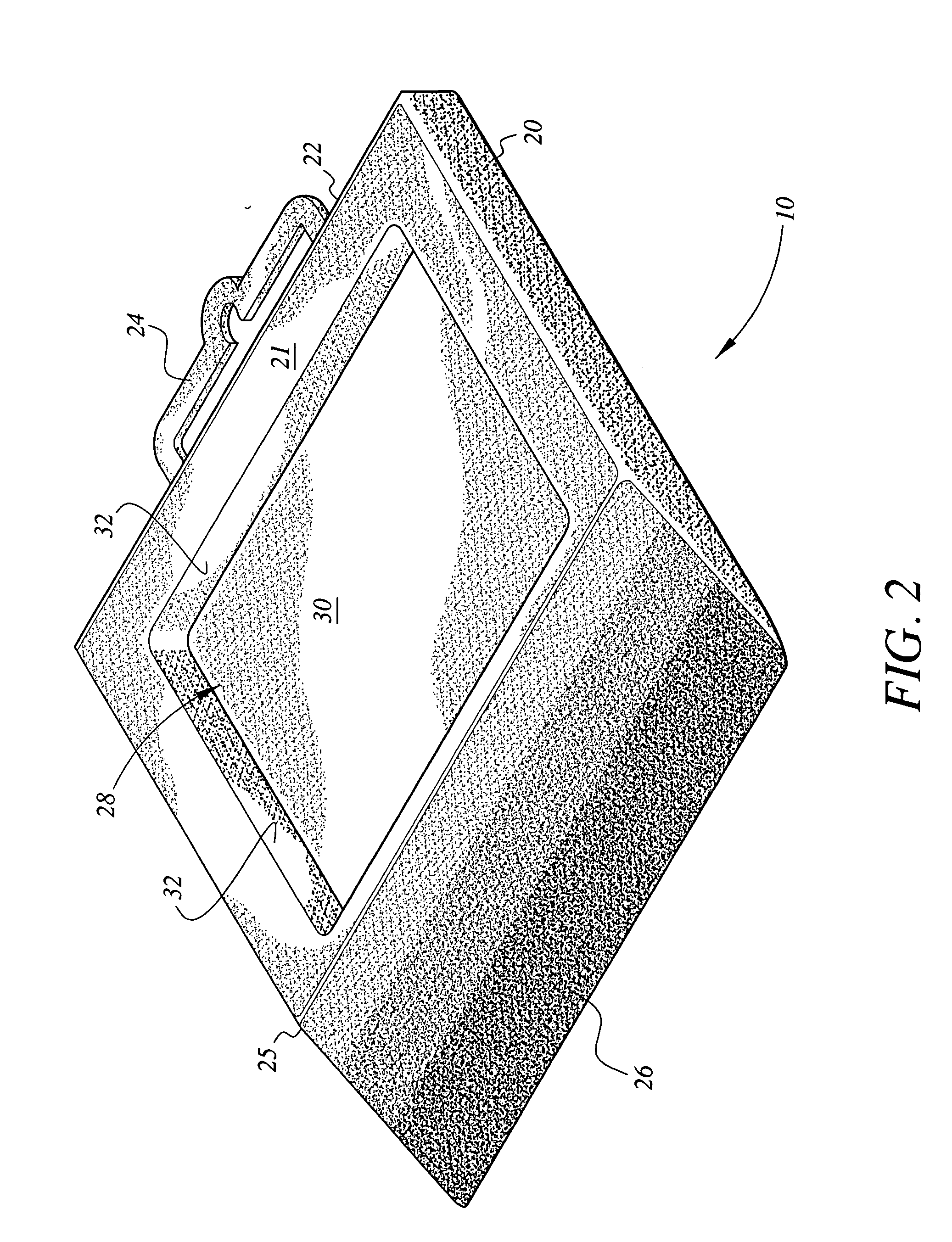
[0032] The present invention is a pallet jack stop, designated generally as 10 in the drawings. The pallet jack stop 10 is designed to immobilize the pivot wheel(s) 122 on a warehouse style pallet jack 114, as shown in FIG. 1. Referring first to FIGS. 2 and 3, the pallet jack stop 10 comprises a rectangular body 20 made from dense rubber (natural or synthetic) or similar material having a top side 21 and a bottom surface 40, and a ramp end 25 and a handle end 22 opposite the ramp end 25. In the illustrated embodiment, a handle 24 extends from the handle end 22, and may be formed integrally with the body 20 or may be made as a separate piece and joined to the body of the pallet jack stop 10 by adhesives, ultrasonic welding, heat welding, or other joinery techniques conventionally known in the art. Optionally, the handle 24 may be positioned elsewhere on the body 20 of the pallet jack stop 10, or may be eliminated entirely.

[0033] A sloping ramp portion extends from the ramp end 25, s...


PUM


Abstract

The pallet jack stop is a rectangular, durable, portable, molded, rubber body having a wheel cradle for restraining the movement of the pivot wheel(s) of a warehouse style pallet jack defined in a top side of the body. One edge of the body is beveled or ramped. The opposite side of the cradle may include a handle integrally constructed with the body of the device. The handle may be located elsewhere on the body of the pallet jack stop, or may be eliminated entirely. Recesses are formed in a bottom surface of the pallet jack stop body, whereby the amount of material used in construction of the pallet jack stop is reduced to reduce the weight and manufacturing costs of the pallet jack stop. The cradle's construction meets all safety and environmental requirements and is structurally stable for heavy cyclic loading under a wide range of environmental conditions.

Description

CROSS-REFERENCE TO RELATED APPLICATION [0001] This application is a continuation-in-part of U.S. patent application Ser. No. 10 / 350,220, filed Jan. 24, 2003.BACKGROUND OF THE INVENTION [0002] 1. Field of the Invention [0003] The present invention relates to wheel-based warehouse style pallet jacks, and particularly to a pallet jack stop formed by a wheel cradle and a small ramped approach defined on one side. The device secures the main pivoting wheel of the pallet jack, thus preventing it from rolling around uncontrollably, endangering personnel and property. [0004] 2. Description of the Related Art [0005] When storing or transporting goods in bulk quantities, it often becomes necessary to place such goods on pallets in order protect them from damage and facilitate their movement. The pallets are usually made of wood and elevate the bulk materials several inches above the warehouse floor, freight train car, or truck bed. The pallets, in turn, can be lifted and moved by warehouse pe...

Claims


Application Information

Patent Timeline
Patent Type & Authority Applications(United States)
IPC IPC(8): B60T3/00B66F7/24
CPCB66F7/243B60T3/00
Inventor FENYVES, MARVINMOSBY, GORDON
Owner FENYVES MARVIN
Why Eureka
Try Eureka