
Photo cell and a gain control method thereof

a gain control and photocell technology, applied in the field of photocells constituting photocell arrays, can solve the problems of deterioration of light efficiency of photocells and decrease of phototransistor sensitivity, and achieve the effect of simple design

Inactive Publication Date: 2005-09-01
SAMSUNG ELECTRO MECHANICS CO LTD
View PDF2 Cites 2 Cited by
  • Summary
  • Abstract
  • Description
  • Claims
  • Application Information

AI Technical Summary

Benefits of technology

[0029] In order to solve the above and / or other problems, it is an aspect of the present invention to provide a photocell forming a photocell array, the photocell being simple in designing and being able to operate a sub-PNP type transistor at an optimized state.
[0030] It is another aspect of the present invention to provide a photocell generating a more stable phototransistor bias voltage by increasing a voltage of a base terminal of the phototransistor, which is an amplifying element of a photo element, to improve light effectiveness and sensitivity of the phototransistor.

Problems solved by technology

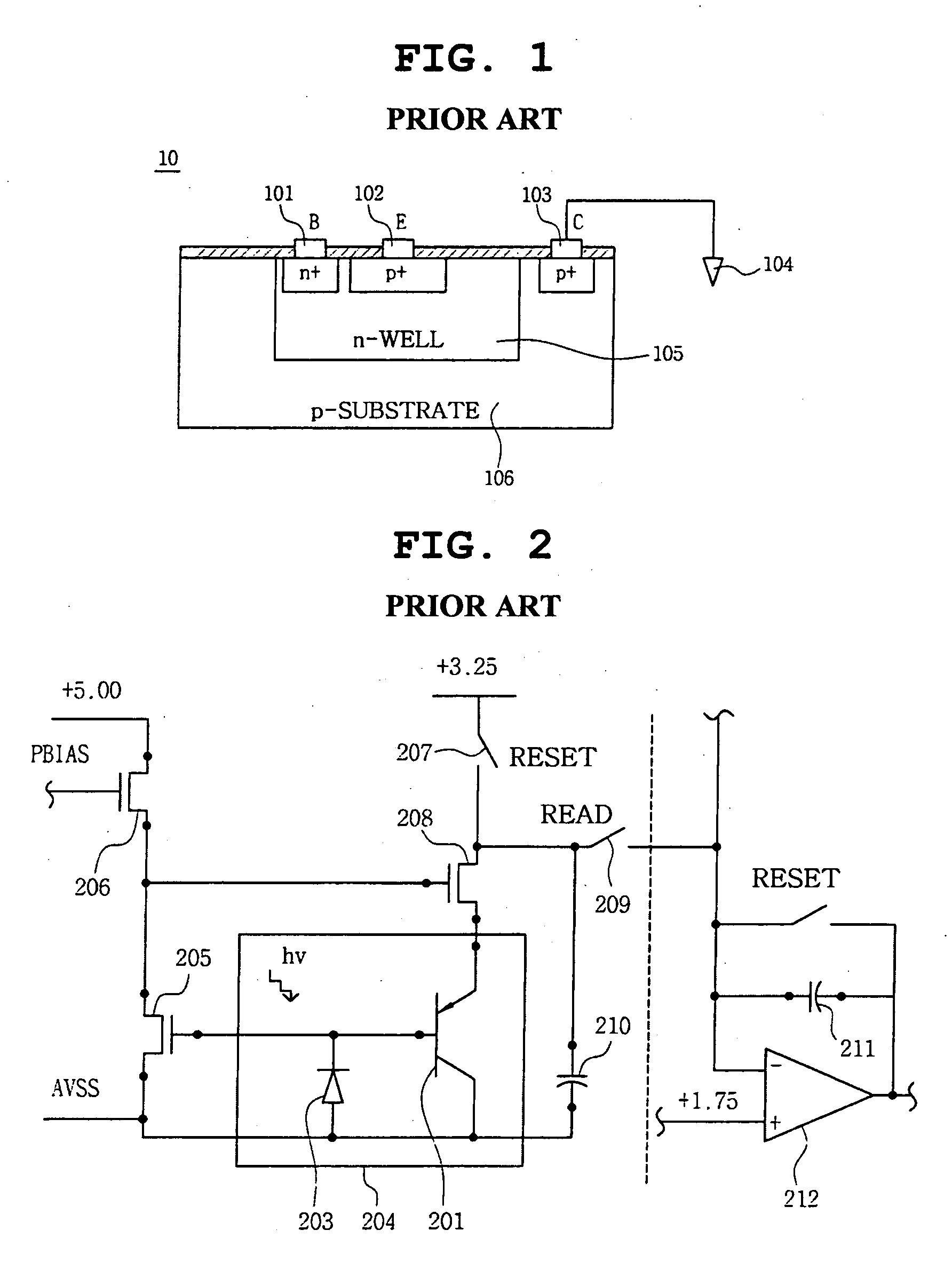
However, since a voltage of the base terminal of the phototransistor shown in U.S. Pat. No. 5,769,384 is low, the sensitivity of the phototransistor is decreased, and light effectiveness of the phototransistor deteriorates.

Method used


Image

  • Photo cell and a gain control method thereof
  • Photo cell and a gain control method thereof
  • Photo cell and a gain control method thereof

Examples


Embodiment Construction

[0068] Reference will now be made in detail to the embodiments of the present invention, examples of which are illustrated in the accompanying drawings, wherein like reference numerals refer to the like elements throughout. The embodiments are described below in order to explain the present invention by referring to the figures.

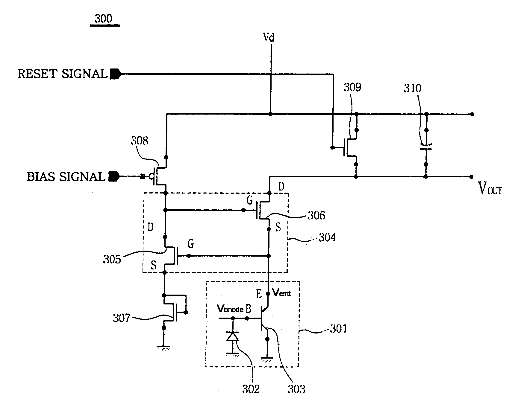
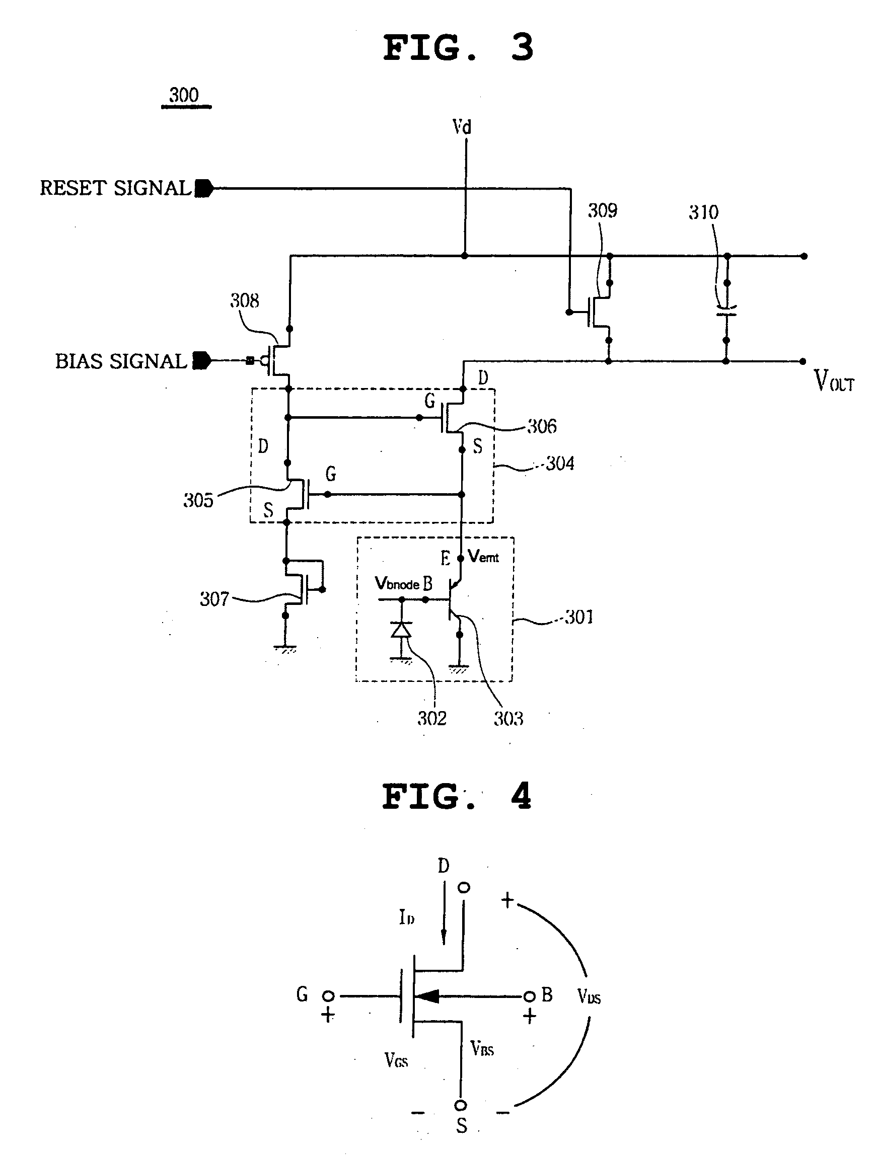
[0069]FIG. 3 is a view showing a photocell 300 according to an embodiment of the present invention.

[0070] A photocell element 301 may include a photodiode 302 to receive a light signal, generate a current in response to the received light signal, and amplify the generated current, and a phototransistor 303 to amplify the current generated from photodiode 302 as an amplifying element.

[0071] A voltage control circuit 304 may include a first MOS transistor 305 and a second MOS transistor 306 to maintain a base terminal voltage Vbnode constant according to this embodiment.

[0072] As shown in FIG. 3, the voltage control circuit 304 may include the first MOS tra...


PUM


Abstract

A photocell used with an optical mouse, a CMOS sensor of a digital camera module, or a scanner includes a photo element in which a feedback circuit to maintain a base terminal voltage of the photo element constant, is not directly connected to a base terminal to control the voltage to directly maintain an emitter terminal voltage so that a stable bias voltage is generated compared to a conventional photo element. The photocell includes a stepping element to increase the voltage applied to the base terminal of the photocell, thereby improving sensitivity of the photocell and increasing effectiveness of light.

Description

CROSS-REFERENCE TO RELATED APPLICATIONS [0001] This application claims the benefit of Korean Patent Application No. 2004-13106 filed with the Korea Industrial Property Office on Feb. 26, 2004, the disclosure of which is incorporated herein by reference. BACKGROUND OF THE INVENTION [0002] 1. Field of the Invention [0003] The present invention relates to a photocell constituting a photocell array, and more particularly, to a photocell used with an optical mouse, a CMOS sensor of a digital camera module, or a scanner to maintain a uniform base terminal voltage of a phototransistor which is an amplifying element to form the photo element using a voltage stepping element and a voltage regulating loop circuit, to simultaneously generate a more stable bias voltage than a conventional circuit by increasing a base terminal voltage of the phototransistor, and to increase a light effectiveness by increasing a light sensitivity of the phototransistor. [0004] 2. Description of the Related Art [0...

Claims


Application Information

Patent Timeline
Patent Type & Authority Applications(United States)
IPC IPC(8): H01J40/14H01L27/14H01L27/146H01L31/10H03F3/16
CPCH01L27/14603H01L27/14609H04N3/155H01L27/14689H01L27/14643H04N25/571H04N25/77B60N3/02G09F19/00G09F7/02G09F23/00B60Y2200/143B60Y2200/31
Inventor KIM, CHANG-HYUNCHOI, WON-TAE
Owner SAMSUNG ELECTRO MECHANICS CO LTD
Learn More