
Spray device

Inactive Publication Date: 2005-09-01
SHANGHAI ELECTRICGROUP CORP
View PDF15 Cites 5 Cited by
  • Summary
  • Abstract
  • Description
  • Claims
  • Application Information

AI Technical Summary

Benefits of technology

[0007] An object of the present invention is to provide a spray device for applying liquid to a printing press while reducing waste and / or misting.
[0009] The present invention provides a spray device for a printing press comprising: a liquid inlet orifice for receiving a liquid, a gas inlet orifice for receiving a gas disposed downstream from the liquid inlet orifice, and an exit orifice disposed at a distance from a surface of the printing press, such as a surface of a dampening cylinder. The spray device, thus allows for the entrainment of a gas, such as air, into the liquid before the mixture is sprayed toward the surface of the printing press.
[0010] The spray device may also include an internal passage communicating with the liquid inlet orifice, the gas inlet orifice, and the exit orifice. Particularly for liquids having low surface tensions, the presence of tiny gas bubbles may improve the characteristics of the spray, such as by creating clusters of droplets that have more mass and are less susceptible to drifting.
[0012] By having an insert member defining the gas and liquid inlet orifices and a separate nozzle tip defining the exit orifice of the spray device, the size and shape of the inlet orifices can be controlled separately from the exit orifice. Thus, the flow rate of the liquid and / or the gas into the nozzle, which is primarily controlled by the size of the respective inlet orifices, can be controlled separately from the characteristics of the spray pattern, which is primarily controlled by the geometry of the exit orifice in the nozzle tip. By replacing the insert member with a different insert member having a smaller liquid inlet orifice, for example, the liquid flow rate through the nozzle may be reduced. The nozzle tip may also be replaced to include an exit orifice with the appropriate size and geometry to accommodate the reduced flow rate and to produce an optimal spray pattern for that reduced flow rate. The nozzle tip is preferably held adjacent to the insert member by a connecting device, such as a screw cap, that is removeably attached either to the insert member itself or to the body member of the spray device, to provide for readily changing the nozzle tip and / or the insert member.

Problems solved by technology

Droplets that are too small contribute to misting, and may never reach the surface of the dampening roll.
In addition, droplets that are too large or dense may cause splash-back when they strike the cylinder surface.
The reduction in surface tension, however, also tends to decrease droplet size in the spray, and thus increase misting and the resultant waste of the liquid during use.

Method used


Image

  • Spray device
  • Spray device
  • Spray device

Examples


Embodiment Construction

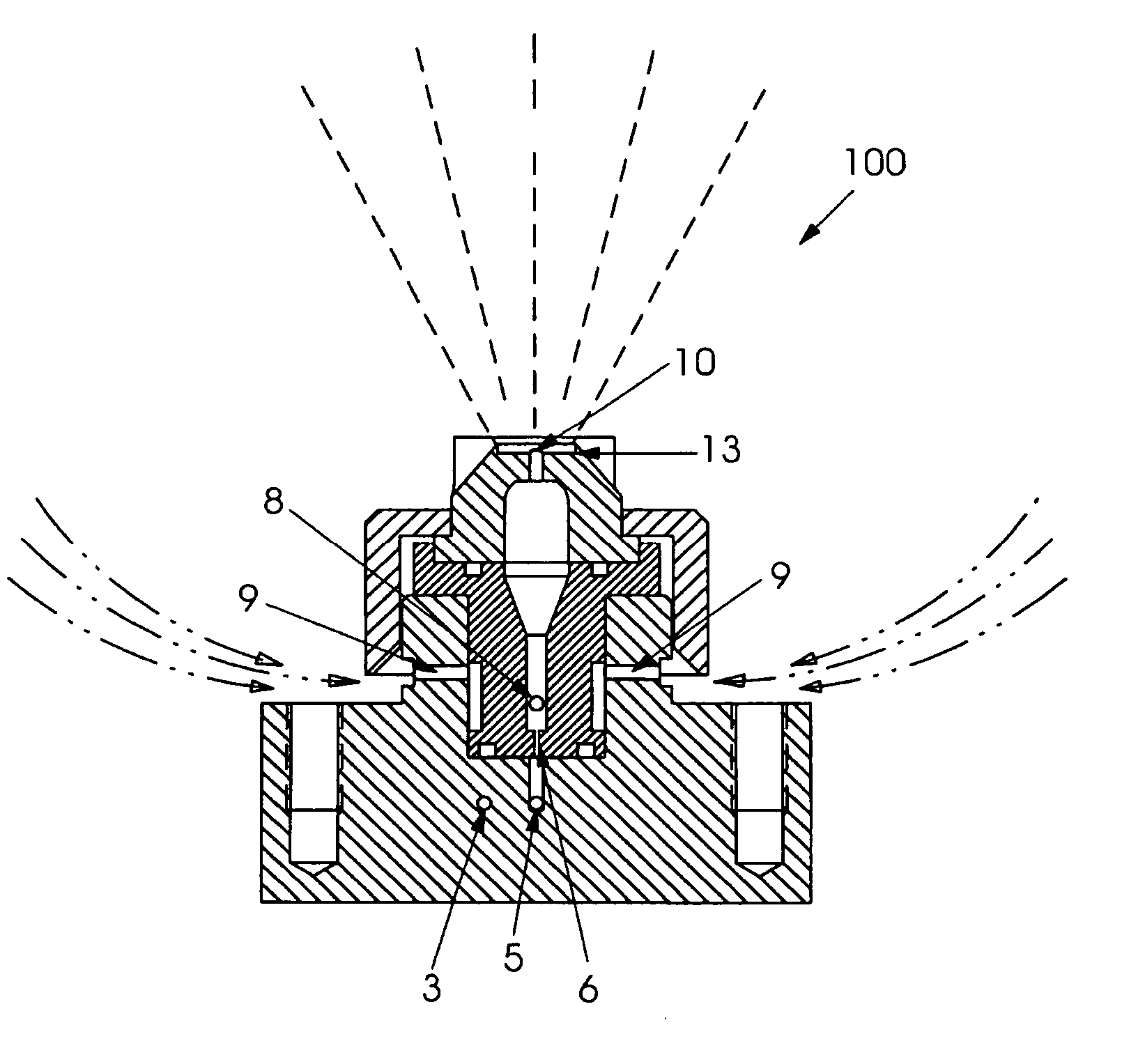
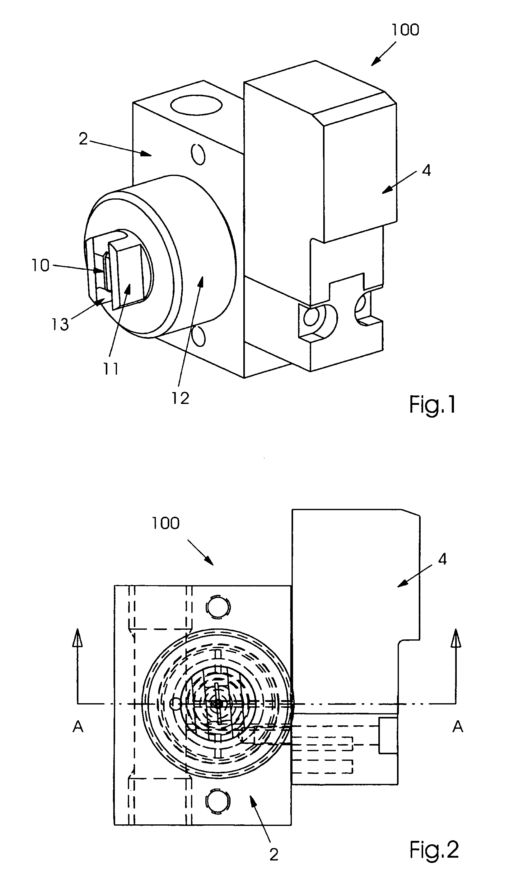
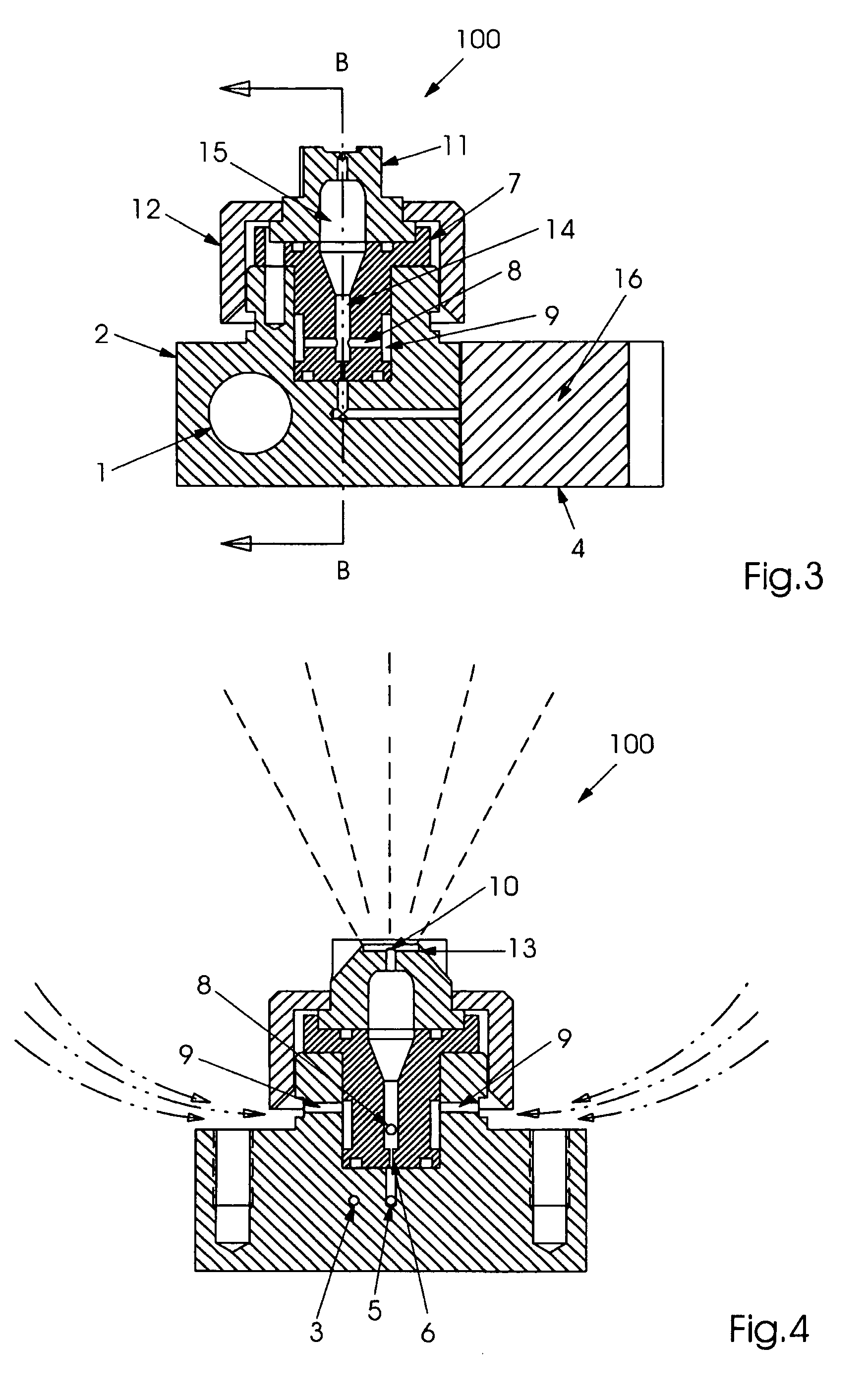
[0028]FIGS. 1 and 2 show an exemplary embodiment of a spray device 100 of the present invention. Screw cap 12 is threaded onto body member 2 and holds nozzle tip 11 in place. Exit orifice 10 is visible on the front on spray device 100 as is flat-bottom slot 13. Solenoid 4 is mounted to the side of body 2 for actuating a valve element 16 inside of solenoid 4, to repeatedly interrupt a flow of liquid through the spray device and cause pulsed spraying.

[0029] The paths of the liquid and gas through the spray device are visible in the sectional views of FIG. 3 (showing a sectional view through line A-A of FIG. 1) and in FIG. 4 (showing a sectional view through line B-B of FIG. 3). A liquid enters the body member 2 through liquid supply conduit 1. Where the spray device is used for dampening a plate cylinder on a printing press, the liquid is typically a fountain solution of water that includes additives to reduce its surface tension. In other applications of the spray device, the liquid...


PUM

PropertyMeasurementUnit
Pressureaaaaaaaaaa
Flow rateaaaaaaaaaa
Sizeaaaaaaaaaa

Abstract

A spray device for a printing press includes a liquid inlet orifice for receiving a liquid, a gas inlet orifice for receiving a gas disposed downstream from the liquid inlet orifice, and an exit orifice disposed at a distance from a surface of the printing press. In addition, a method for applying a liquid to a surface of a printing press, includes the steps of providing a liquid to a liquid inlet orifice of a spray device, providing a gas to a gas inlet orifice of the spray device; and spraying a mixture of the liquid and gas onto the surface of the printing press.

Description

BACKGROUND OF THE INVENTION [0001] The present invention relates generally to printing presses and more particularly to a spray device on a printing press for spraying a surface of the press. [0002] Spray devices have been used in conjunction with offset printing machines, especially web offset printing machines, to apply liquid to a cylinder surface. A plurality of spray devices are typically mounted on a spray bar, which holds the spray devices at a distance from a surface of the cylinder. Spray devices are used to dampen the plate cylinder with water or a fountain solution as part of the printing process. Typically, the spray devices spray the liquid directly onto a surface of a dampening cylinder. A train of two more dampening cylinders is then used to spread the liquid into a continuous film and to transport the liquid to the plate cylinder. The liquid adheres to the hydrophilic areas on the surface of the plate cylinder to resist the deposition of ink on those areas. Spray dev...

Claims


Application Information

Patent Timeline
IPC IPC(8): B01D47/02B01F3/04B05B7/02B05B7/04B05B7/08B41F7/30
CPCB05B7/0425B41F7/30B05B7/0884
Inventor BLANEY, KEN FRANCISWORONIAK, MICHAEL THOMAS
Owner SHANGHAI ELECTRICGROUP CORP
Learn More