Connector assembly

a technology of connecting rods and connectors, applied in the direction of pipe couplings, pipe elements, couplings, etc., can solve the problems of inability to tell whether or not, inadvertent release, etc., and achieve the effect of relative rotation between the spring clip and the female elemen

Inactive Publication Date: 2005-09-01
ONO TAKASHI
View PDF0 Cites 36 Cited by
  • Summary
  • Abstract
  • Description
  • Claims
  • Application Information

AI Technical Summary

Benefits of technology

[0038] Therefore, it is obvious that the relative rotation between the spring clip and the female element is prevented when the U-shaped spring clip is in the fastening position. On the other hand, the relative rotation between the male element...

Problems solved by technology

However, all known embodiments intend to provide an easily connectable assembly, which is inexpensive to manufacture and entail simple designs, there is no means for restraining a rotational movement between the male and female element in the circumferential direction, so that relative rotation between the male and female element can occur by shocks and vibration on the automotive vehicle, whereby it produces unexpected wear of the annular sealing element and there is inclined to leak at a connecting position, there is also inclined to leak at a connecting position by the relative rotation between the male an...

Method used


Image

  • Connector assembly
  • Connector assembly
  • Connector assembly

Examples


first embodiment

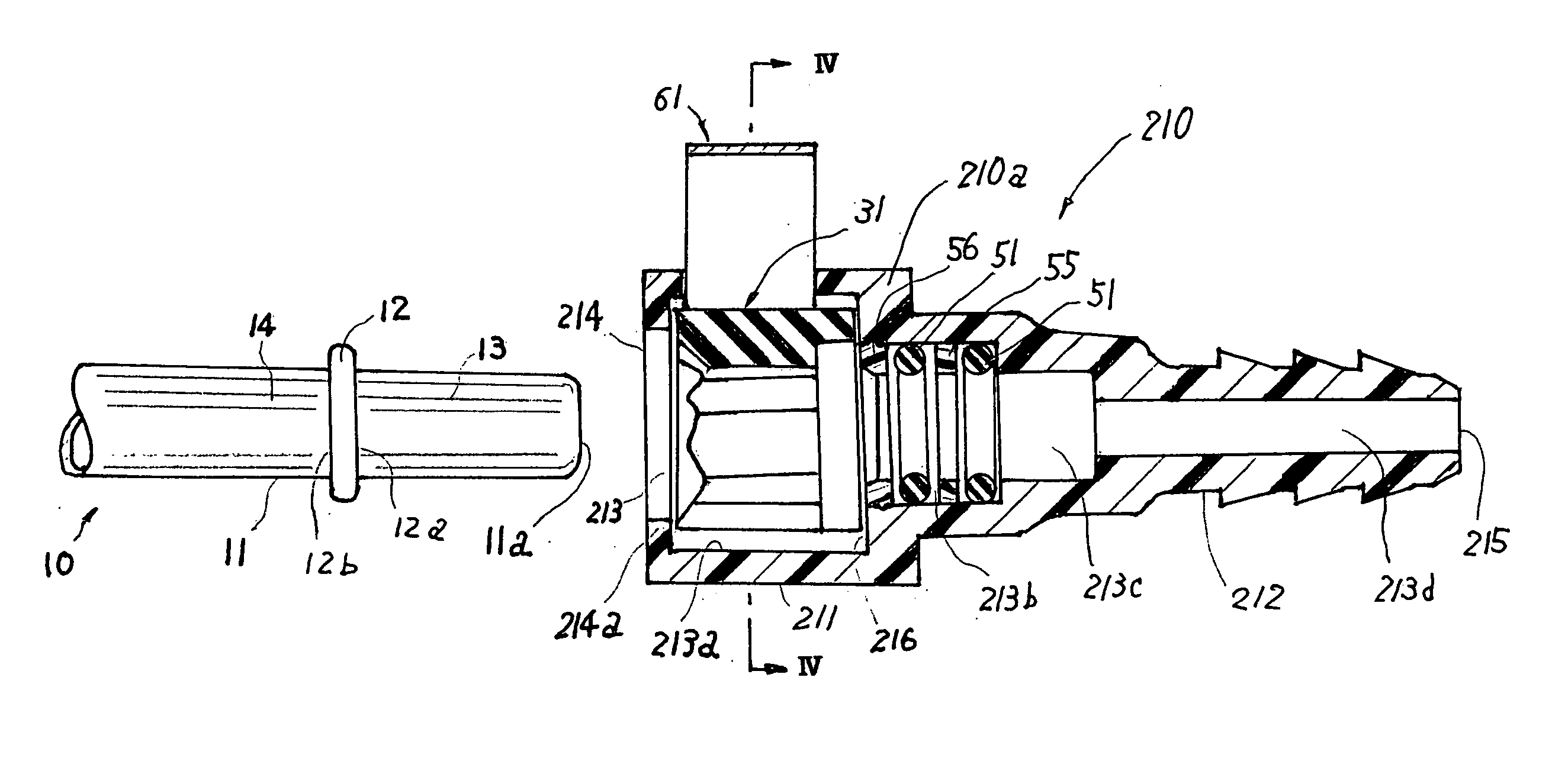
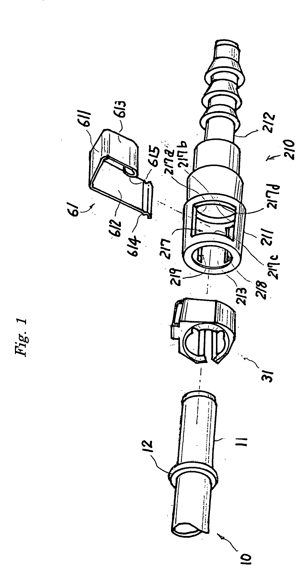
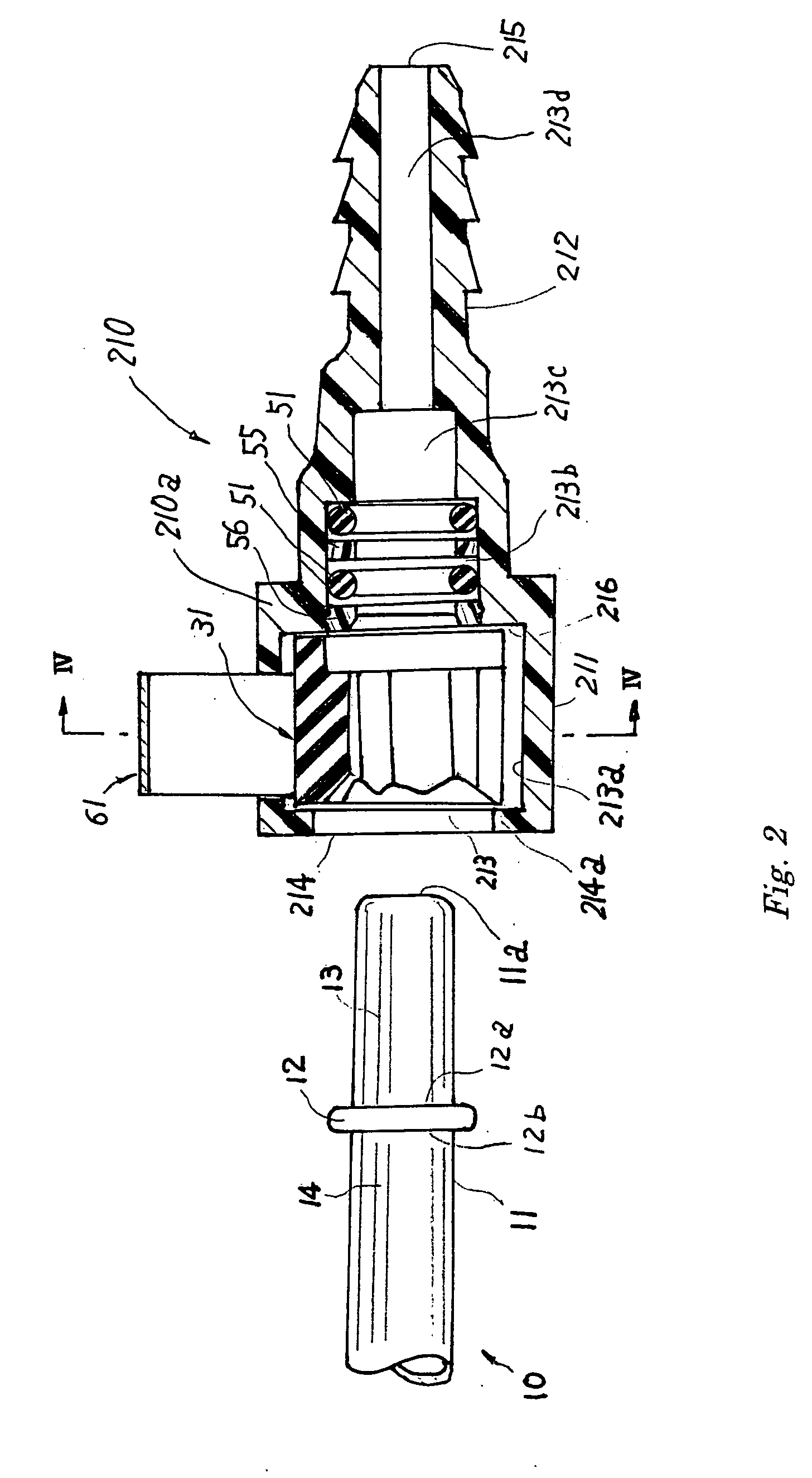
[0098] as the retainer 31 made from large high frictional material, this retainer 31 can function as a large high friction element too when the generally C-shape retainer 31 is fastened against the insert end portion 11 by the U or C-shape clip 61, as describe hereafter. In addition, simultaneously with the insertion of the insert end portion 11 of the conduit 10 into the connected portion of the receipt end portion 211 of the female element 210, O-rings 51 and 51 fluidly sealingly engage an outer periphery of the front area 13 of the insert end portion 11 as best shown in FIG. 8 of the drawing. Thus the O-rings 51 and 51 form a fluid tight seal between the conduit 10 and the female element 210.

[0099] Finally, the wave shaped engaging projection portion 614 of the first leg 612 can be passed through the poky going aperture 219 from the enlarged diameter internal bore potion 213a to an outside of the receipt end portion 211 for engaging with the sidewall of the poky going aperture 2...

second embodiment

[0139] Also, opposite arcuate shaped sloping lead areas 33 and 33 are positioned concentric with a center axis within the enlarged diameter internal bore potion 223a when the U-shaped fastener device 60 is in the open position as shown in FIG. 17. More particularly, a connector assembly of the second embodiment is designed to produce an axially space 226a between the radially inwardly extending annular surface 226 and an other side surfaces 627 of the fastener body 62 as shown in FIG. 14. This space 226a serves for receiving an annular projection 12 on the insert end portion 11 when the male element 210 axially inserts into the receipt end portion 211.

[0140] When an assembly worker forces one's way the U-shaped fastener device 60, can be moved from the open position until a fastening position as shown in FIG. 19. A pair of the second engaging projections 625 and 625 formed with U-shaped fastener body 62 resiliently are engaged the pair of first edge portion 228a, 228a of the opposit...


PUM


Abstract

A connector assembly includes a mating male and female element and further includes a retainer made from large high friction material, a generally annular sealing element and an anti-rotation mechanism for restraining the relative rotation between the male element and female element. The female element includes a housing formed with an axial bore for receive an insert end portion of the male element at a receipt end portion, the receipt end portion having an enlarged diameter internal bore potion adapt to receive the retainer fore locking a radially enlarged annular projection on the insert end portion of the male element, which is secured the receipt end portion of the female element.

Description

BACKGROUND OF THE INVENTION [0001] 1. Field of Invention [0002] The present invention relates to a connector assembly, more particularly, to a connector assembly providing with a means for restraining relative rotation between a male element and a female element by an intervention of a large high friction element. [0003] 2. Description of the Prior Art [0004] There are many previously known quick connector assembly which are typically includes a tubular female element, a male element and many type of retainer elements for securing the male element within the female element. More particularly, the tubular female element adapted for selective locking connect engagement with a tubular male element. The tubular male element typically includes a insert end portion terminating in a tip end and having a radially extending annular projection spaced from the tip end. [0005] The tubular female element formed with an axially extending stepped bore for receive the male element at the receipt en...

Claims


Application Information

Patent Timeline
IPC IPC(8): F16L37/00F16L37/12F16L37/14
CPCF16L37/088F16L2201/10F16L37/144F16L37/0985F16L37/0885
Inventor ONO, TAKASHI
Owner ONO TAKASHI
Why Eureka
Try Eureka