Backlight Module

a backlight module and backlight technology, applied in the field of backlight modules, can solve the problems of reducing the optical grade, adverse to cost control, increasing the manufacture cost, etc., and achieves the effects of high strength, excellent heat dissipation performance, and simple structur

Inactive Publication Date: 2013-12-05
TCL CHINA STAR OPTOELECTRONICS TECH CO LTD
View PDF4 Cites 4 Cited by
  • Summary
  • Abstract
  • Description
  • Claims
  • Application Information

AI Technical Summary

Benefits of technology

[0009]Thus, an object of the present invention is to provide a backlight module, which has a simple structure, excellent performance of heat dissipation, high strength, and low cost and is helpful for enhancing optic grade.
[0010]Another object of the present invention is to provide a backlight module, which has a simple structure, excellent performance of heat dissipation, high strength, and low cost, is helpful for enhancing optic grade, and is easy to fix a light guide plate.
[0021]The efficacy of the present invention is that the present invention provides a backlight module, which comprises a backplane that is formed by jointing a main body and a bracket. By arranging two rows of bolts to fix the main body and the bracket, relative rotation between the main body and the bracket can be effectively prevented. Meanwhile, connecting the main body and the bracket also effects fixing the light guide plate so as to eliminate a separate arrangement of fixing structure for the light guide plate thereby lowering down the manufacture cost. Further, the main body of the backplane is made of a high strength material and the bracket is made of a high thermal conductivity material. This ensures the strength of the backplane and also exhibits excellent thermal conduction to thereby enhance the grade of the backlight module.

Problems solved by technology

This leads to a potential situation that the main body 202 and the first bracket 204 may get rotatable relative to each other, and consequently, the flatness of the backplane 200 deteriorates, making the optic grade lowered and being adverse to cost control.
Again, the same drawback as that discussed above exists.
This, to some extents, increases the manufacture cost.

Method used


Image

  • Backlight Module
  • Backlight Module
  • Backlight Module

Examples


Embodiment Construction

[0030]To further expound the technical solution adopted in the present invention and the advantages thereof, a detailed description is given to a preferred embodiment of the present invention and the attached drawings.

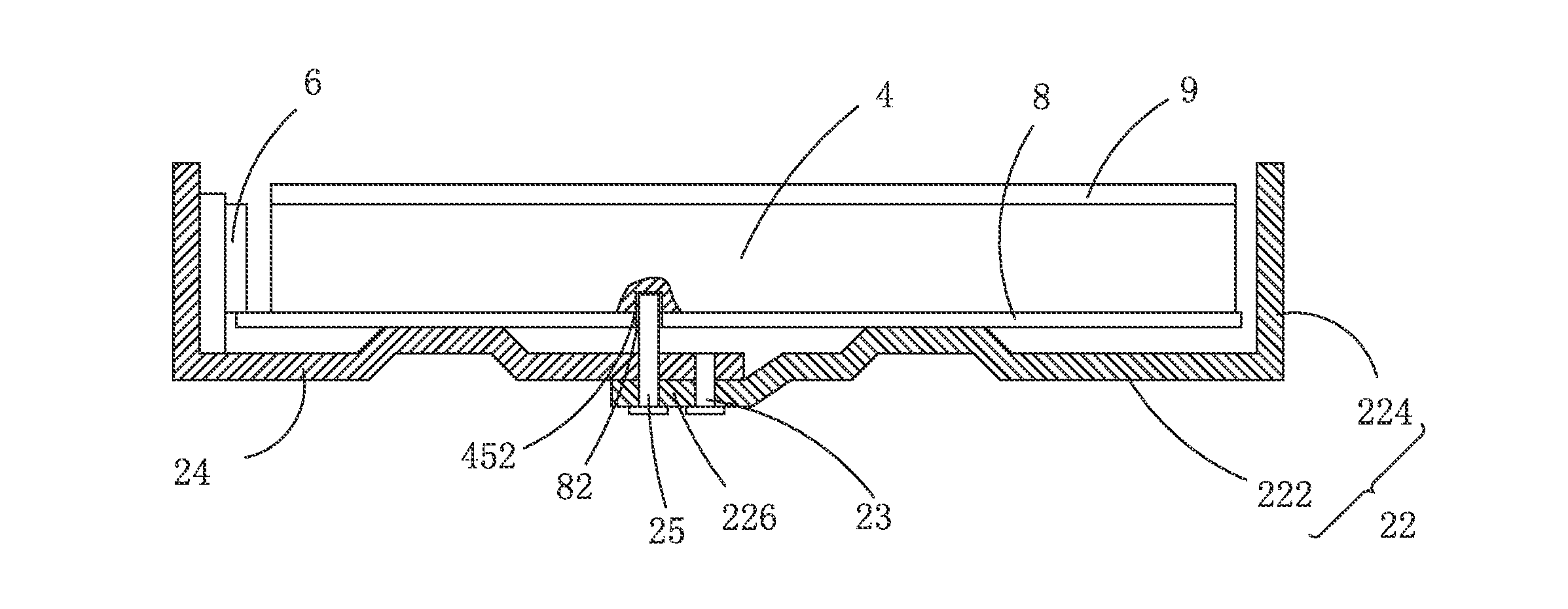
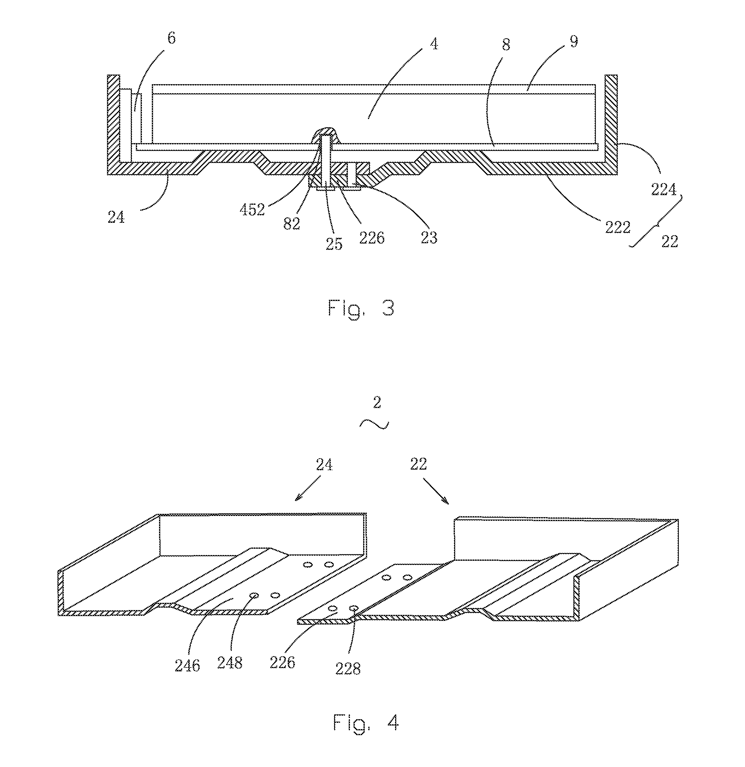
[0031]Referring to FIGS. 3 and 4, the present invention provides a backlight module, which comprises: a backplane 2, a light guide plate 4 arranged inside the backplane 2, and a first backlight source 6 arranged inside the backplane 2.

[0032]The backplane 2 comprises a main body 22 and a first bracket 24 connected to the main body 22. The main body 22scomprises a base plate 222 and a side plate 224 integrally connected with the base plate 222. The base plate 222 comprises a first lap section 226 adjacent to an edge of the first bracket 24. The first bracket 24 comprises a first connection section 246 adjacent to the base plate 22 and corresponding to the first lap section 226. To assemble, the first lap section 226 is lapped on the first connection section 246 and is jo...


PUM


Abstract

The present invention provides a backlight module, which includes a backplane, a light guide plate arranged inside the backplane, and a first backlight source arranged inside the backplane. The backplane includes a main body and a first bracket connected to the main body. The main body includes a base plate, which includes a first lap section adjacent to an edge of the first bracket. The first bracket includes a first connection section adjacent to an edge of the base plate and corresponding to the first lap section. The first lap section and the first connection section are lapped on each other. A plurality of first and second bolts joints the first lap section and the first connection section together. The plurality of first and second bolts is arranged in two rows. The backplane is composed of the main body and the bracket that are jointed by two rows of bolts.

Description

BACKGROUND OF THE INVENTION[0001]1. Field of the Invention[0002]The present invention relates to the field of liquid crystal displaying, and in particular to a backlight module.[0003]2. The Related Arts[0004]Liquid crystal display (LCD) has a variety of advantages, such as thin device body, low power consumption, and being free of radiation, and is thus widely used. Most of the LCDs that are currently available in the market are backlighting LCDs, which comprise a liquid crystal display panel and a backlight module. The working principle of the liquid crystal display panel is that liquid crystal molecules are interposed between two parallel glass substrates and a plurality of vertical and horizontal fine electrical wires is arranged between the two glass substrates, whereby the liquid crystal molecules are controlled to change direction by application of electricity in order to refract light emitting from the backlight module for generating images. Since the liquid crystal display p...

Claims


Application Information

Patent Timeline
Patent Type & Authority Applications(United States)
IPC IPC(8): G09F13/04
CPCG09F13/18G09F2013/147G09F2013/1881G09F2013/222
Inventor KUO, YICHENGZHOU, GEGE
Owner TCL CHINA STAR OPTOELECTRONICS TECH CO LTD
Why Eureka
Try Eureka