Dental implant assembly and abutment thereof

a technology for dental implants and abutments, which is applied in dental implants, dental surgery, medical science, etc., to achieve the effect of hindering the relative rotation, preventing the relative rotation between the abutment and the implant, and preventing the relative rotation more effectively

Active Publication Date: 2017-06-29
CHAN CHIA YI
View PDF14 Cites 1 Cited by
  • Summary
  • Abstract
  • Description
  • Claims
  • Application Information

AI Technical Summary

Benefits of technology

[0031]In sum, the dental implant assembly provided in the present invention features the abutment with a plurality of elastic pressing structures, which is capable to hinder the relative rotation between the abutment and the implant by using the friction force between the elastic pressing structures and the position-restricting wall. In addition, with the help of the end pressing structures, the relative rotation between the abutment and the implant can be prevented more effectively. Moreover, the abutment has an abutment fixing channel extending along the abutment central axis which has a channel diameter greater than the rod diameter such that a tolerance allowable gap would be formed between the abutment fixing channel and the fixing rod. Thereby, even with some error happened in the abutment fixing channel, the fixing element is still able to be fixed to the implant successfully.
[0032]In contrast with the conventional technology, the dental implant assembly provided in the present invention is capable to resolve the problems of the conventional technology, which include the difficulty of fixing the screw into the implant screw hole as the abutment channel has error, and the difficulties of screwing multiple abutments jointed by the dental bridge as an unit into multiple implants screw-fixed in the alveolar bone or removing such abutments from the implants due to the misalignment issue between the individual implants, by using the tolerance allowable gap between the fixing channel and the fixing rod. Additionally, the dental implant assembly provided in the present invention can hinder the relative rotation between the abutment and the implant by using the elastic pressing structure.

Problems solved by technology

In view of the conventional art, which may encounter the difficulty of fixing the screw into the implant screw hole as the abutment channel has error, and the problems of screwing multiple abutments jointed by the dental bridge as one unit into multiple implants which are screw-fixed in the alveolar bone or removing such abutments from the implants due to the misalignment issue among the individual implants.

Method used


Image

  • Dental implant assembly and abutment thereof
  • Dental implant assembly and abutment thereof
  • Dental implant assembly and abutment thereof

Examples


first embodiment

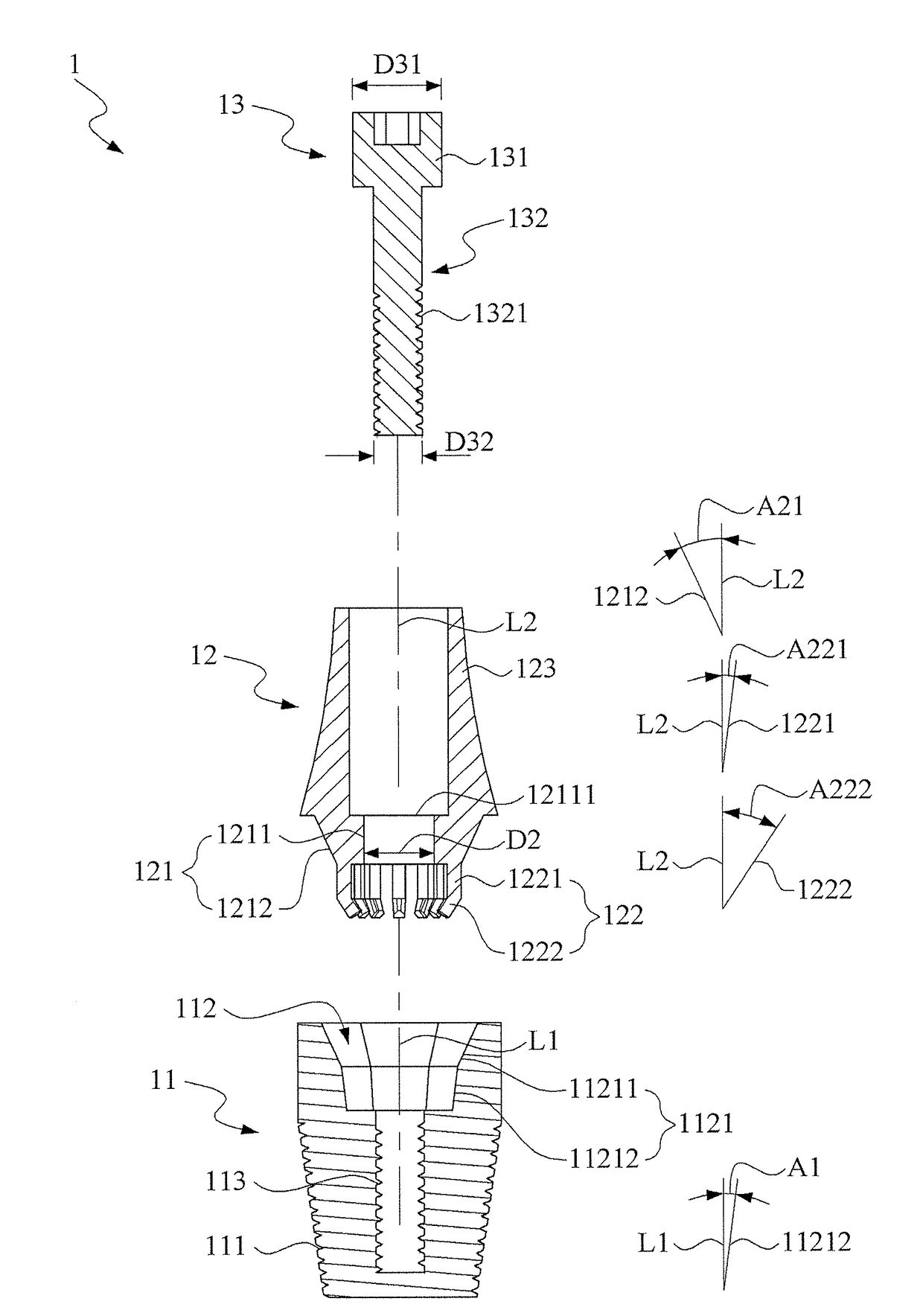
[0047]The implant 11 has an implant outer thread section 111, which is utilized to have the implant 11 screw-fixed to the alveolar bone 2. The implant 11 also has a tapered position-restricting trench 112 surrounded by a position-restricting wall 1121. The tapered position-restricting trench 112 has an implant central axis L1. Preferably, the tapered position-restricting trench 112 is a tapered polygonal position-restricting trench, such as the tapered hexagonal position-restricting trench in the The tapered polygonal position-restricting trench can also be the tapered pentagonal position-restricting trench or the tapered octagonal position-restricting trench for example. It is understood that there are various embodiments regarding the shape of the position-restricting trench, which is not repeated here.

[0048]The position-restricting wall 1121 comprises a tapered wall portion 11211 and a pressed portion 11212. The tapered wall portion 11211 is a polygon-shaped position-restricting...

second embodiment

[0059]Please refer to FIGS. 11 and 12, wherein FIG. 11 is a cross-section view of multiple dental implant assemblys with errors together with the dental bridge provided in accordance with second embodiment of the present invention after the assembling, and FIG. 12 is an enlarge view of the portion B in FIG. 11. As shown, when the dentist places the three implants 11, 11a, 11b as one unit into the alveolar bone 2, human errors are unpreventable such that the three implants 11, 11a, 11b might not be able to be positioned at the ideal position and tilt angle such that the misalignment issue among the implants would be resulted.

[0060]In FIG. 11, these implants 11, 11a, 11b are unparalleled to each other, the implant 11 has a small deviation toward the counterclockwise direction and the implant 11b has a small deviation toward the clockwise direction such that the offset error generated between the implant 11 and the abutment 12 would be different from that generated between the implant ...


PUM


Abstract

A dental implant assembly includes an implant, an abutment, and a fixing element. The implant is placed in the alveolar bone. The abutment is assembled to the implant and includes a tapered position-restricting part and an elastic pressing part. The tapered position-restricting part has an abutment fixing channel substantially matching the tapered position-restricting outer wall of the tapered position-restricting trench. The elastic pressing part includes the elastic pressing structures extended from the tapered position-restricting part. The fixing element includes the fixing head and the fixing rod extended from the fixing head. A tolerance allowable gap is formed between the abutment fixing channel and the fixing rod. As the abutment is assembled to the implant, the elastic pressing structures press against the position-restricting wall first to hinder the relative rotation therebetween; when an offset error exists, the tolerance allowable gap allows the fixing rod to penetrate the abutment fixing channel.

Description

[0001]This application claims the benefit of Taiwan Patent Application Serial No. 104220829, filed Dec. 25, 2015 and Serial No. 105216103, filed Oct. 21, 2016, the subject matter of which are incorporated herein by reference.BACKGROUND OF INVENTION[0002]1. Field of the Invention[0003]The present invention is related to a dental implant assembly and an abutment thereof, and more particularly is related to a dental implant assembly, which uses an elastic pressing structure to prevent relative rotation between the implant and the abutment and adopts the tolerance allowable gap between the fixing rod and the abutment fixing channel to overcome the interference issue due to offset errors between the implant and the abutment, and an abutment thereof.[0004]2. Description of the Prior Art[0005]The history of dental implant technology can be traced back to Medieval. The ancient Egyptian and South American civilization replace the missing teeth using carved ivory and wood. Starting from the 1...

Claims


Application Information

Patent Timeline
Patent Type & Authority Applications(United States)
IPC IPC(8): A61C8/00
CPCA61C8/0057A61C8/006A61C8/0069A61C8/0068
Inventor CHAN, CHIA-YI
Owner CHAN CHIA YI
Why Eureka
Try Eureka