

Multispeed drive unit
a multi-speed drive and transmission unit technology, applied in the direction of gearing details, gearing, transportation and packaging, etc., can solve the problems of system complexity and attendant cost associated with such synchronization, and achieve the effect of facilitating the rotation between
- Summary
- Abstract
- Description
- Claims
- Application Information
AI Technical Summary
Benefits of technology
Problems solved by technology
Method used
Image

Examples
Embodiment Construction
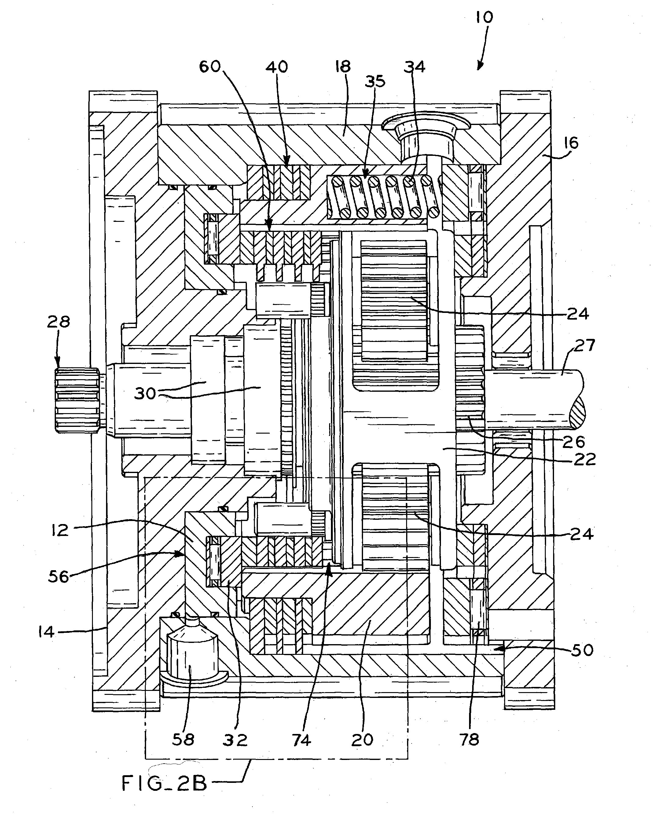
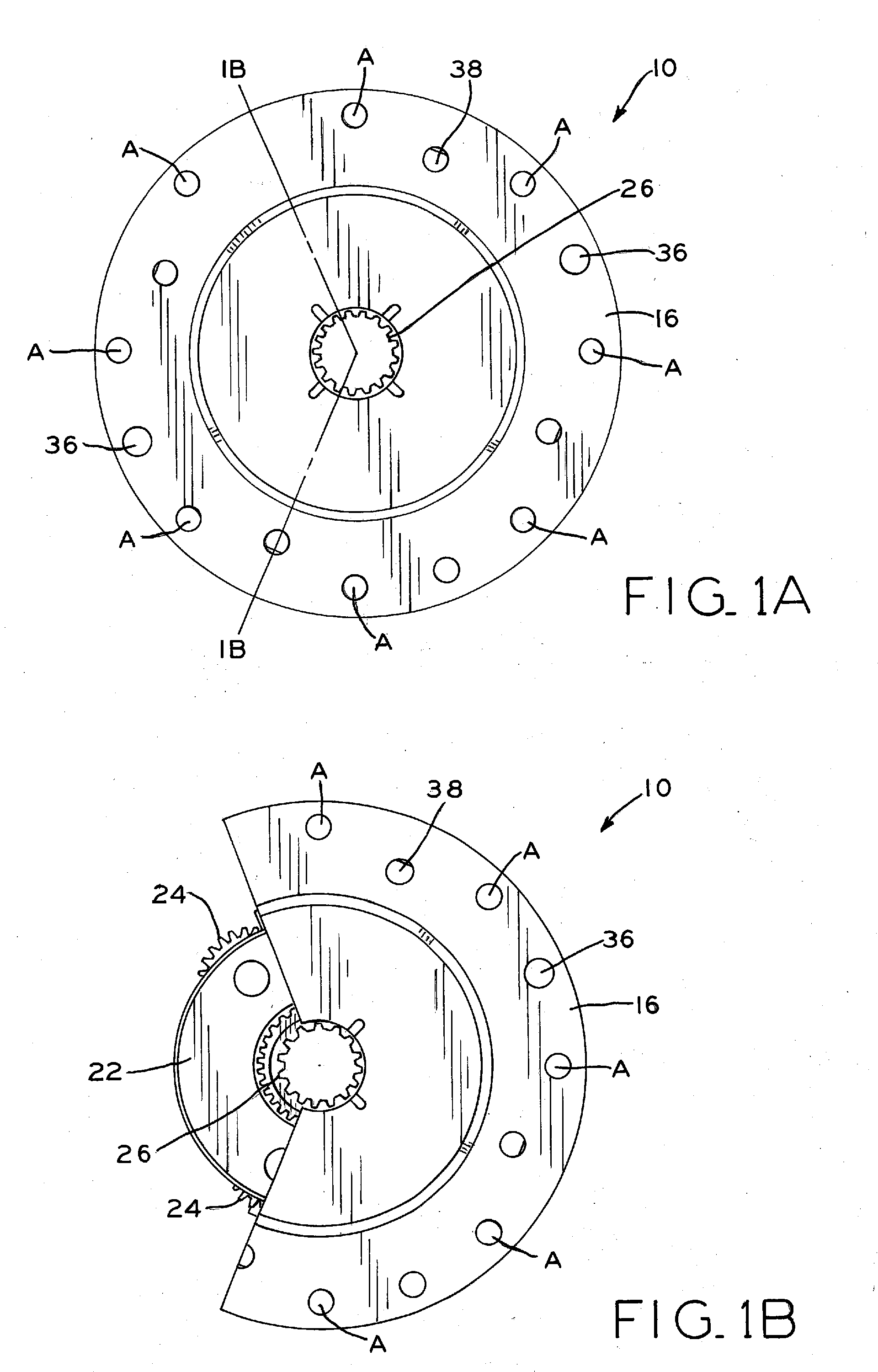
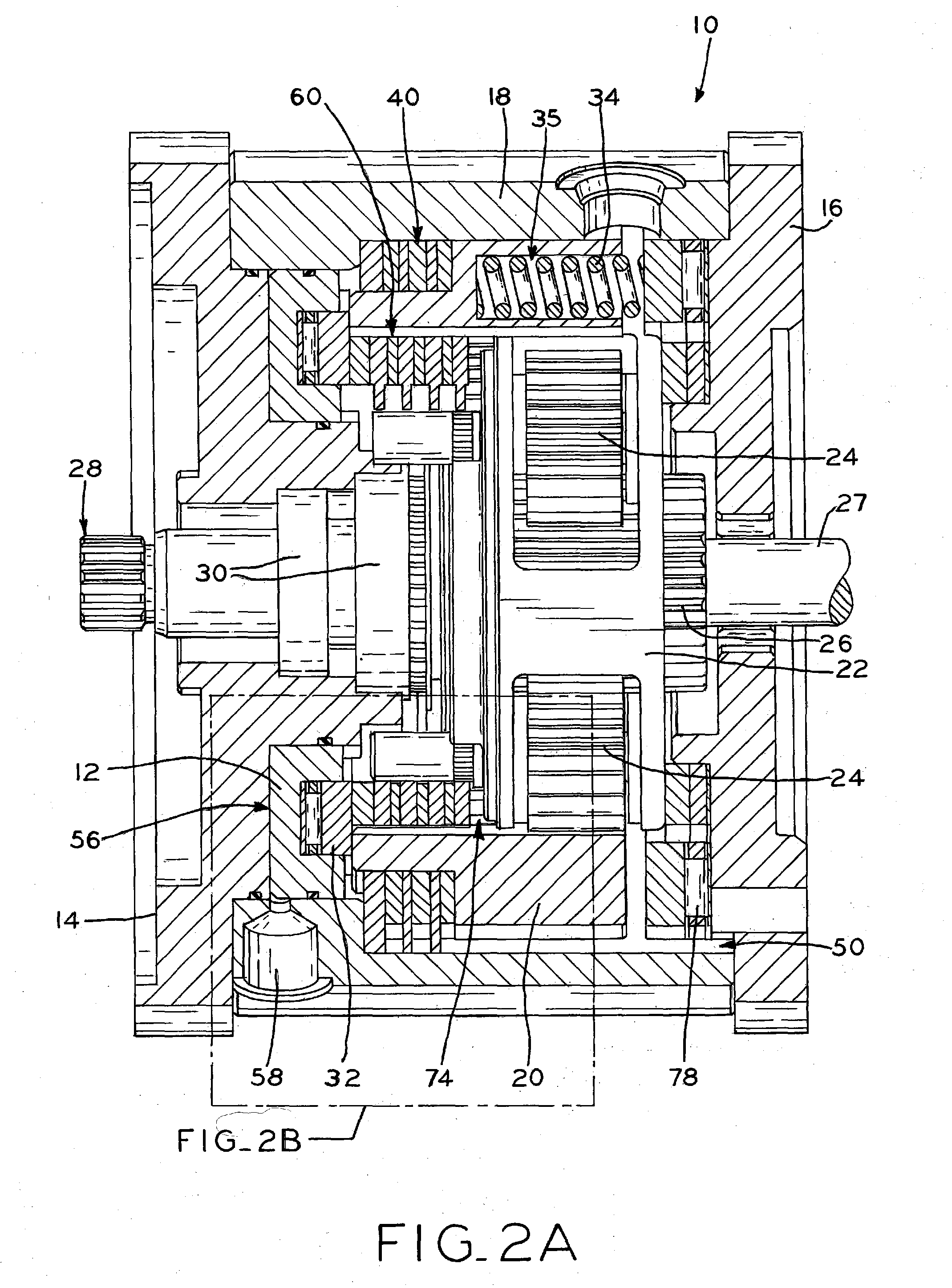
[0055]The present disclosure provides two-speed drive unit 10 which toggles between two differing levels of gear reduction by actuation of a single gearshift piston 12. As described in detail below, gearshift piston 12 toggles between a high-reduction position (FIGS. 2A-2D) and a low-reduction position (FIGS. 3A-3D). In the high-reduction position, gearshift piston 12 causes outer clutch pack 40 to become operably engaged, thereby allowing a planetary gear system to operate inside drive unit 10 to provide a high gear reduction, i.e., output shaft 28 rotates substantially slower than input shaft 27 (FIG. 2A) coupled to the input sun gear 26. In the low-reduction position, gearshift piston 12 allows outer clutch pack 40 to become disengaged and causes clutch pack 60 to become operably engaged, thereby neutralizing the gear reduction functionality of the planetary gear system. Thus, in the low-reduction configuration, drive unit 10 provides no gear reduction, i.e., output shaft 28 rota...
PUM
 Abstract
Description
Claims
Application Information