Wet type multi-plate clutch

a multi-plate clutch and clutch housing technology, applied in the direction of fluid-actuated clutches, non-mechanical actuated clutches, clutches, etc., can solve the problems of o-rings arranged around the piston that may be damaged, connected to the piston may be twisted, and damage the spring, so as to prevent the relative rotation between the piston and the clutch housing, reduce the wear of parts around the piston, and prevent damage to such parts

Inactive Publication Date: 2006-08-03
NSK WARNER
View PDF6 Cites 5 Cited by
  • Summary
  • Abstract
  • Description
  • Claims
  • Application Information

AI Technical Summary

Benefits of technology

[0015] By engaging the projection provided on the outer periphery of the inner diameter portion of the clutch housing with the recessed portion of the piston, the relative rotation between the piston and the clutch housing can be prevented. As a result, the rotation of the piston is eliminated, thereby reducing wear of parts around the piston and thus preventing damage of such parts. Further, a poor operation of the clutch can be prevented.
[0016] Further, by improving an O-ring portion, a compact and low cost wet type multi-plate clutch can be provided.

Problems solved by technology

If the piston is rotated upon engaging the friction engaging elements, due to the rotation of the piston, the O-ring arranged around the piston may be damaged.
Further, due to the rotation of the piston, a spring connected to the piston may be twisted to damage the spring.
As a result, peripheral members may be damaged, thereby causing mal-function of the clutch.
S50-101747, if the pawl portion is provided on the drive plate, the pawl portion abuts against the groove of the piston repeatedly for preventing the relative rotation, with the result that the drive plate may be deformed due to impact or shock.
If such deformation occurs, a normal or correct function of the friction engaging apparatus will be lost.
S50-94345 causes a problem that the number of parts is increased because an additional member as the stop member is provided on the piston.
Further, since the spline groove is formed in the outer diameter portion of the piston, the outer diameter of the piston is increased more than it needs, thereby increasing the cost.
Further, in the above-mentioned Japanese Utility Model Application Laid-open No. 50-101747 and Japanese Utility Model Application Laid-open No. 50-94345, since the relative rotation is prevented by directly engaging the piston with the clutch housing, the relative rotation may not be prevented satisfactorily.

Method used


Image

  • Wet type multi-plate clutch
  • Wet type multi-plate clutch
  • Wet type multi-plate clutch

Examples


Embodiment Construction

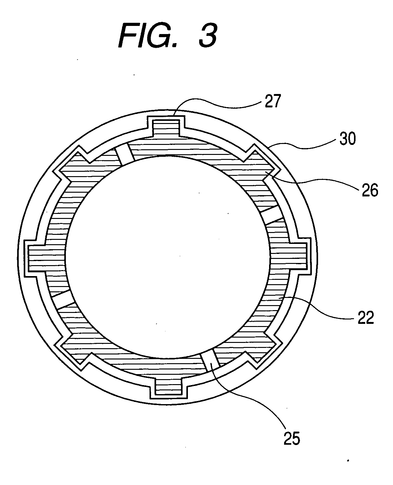
[0020] Now, embodiments of the present invention will be fully explained with reference to the accompanying drawings. Incidentally, in the drawings, the same parts or elements are designated by the same reference numerals. Further, the embodiments which will described later are merely examples of the present invention and do not intend to limit the invention. Further, FIG. 3 is an axial sectional view showing an engaging relationship between a piston and a clutch housing.

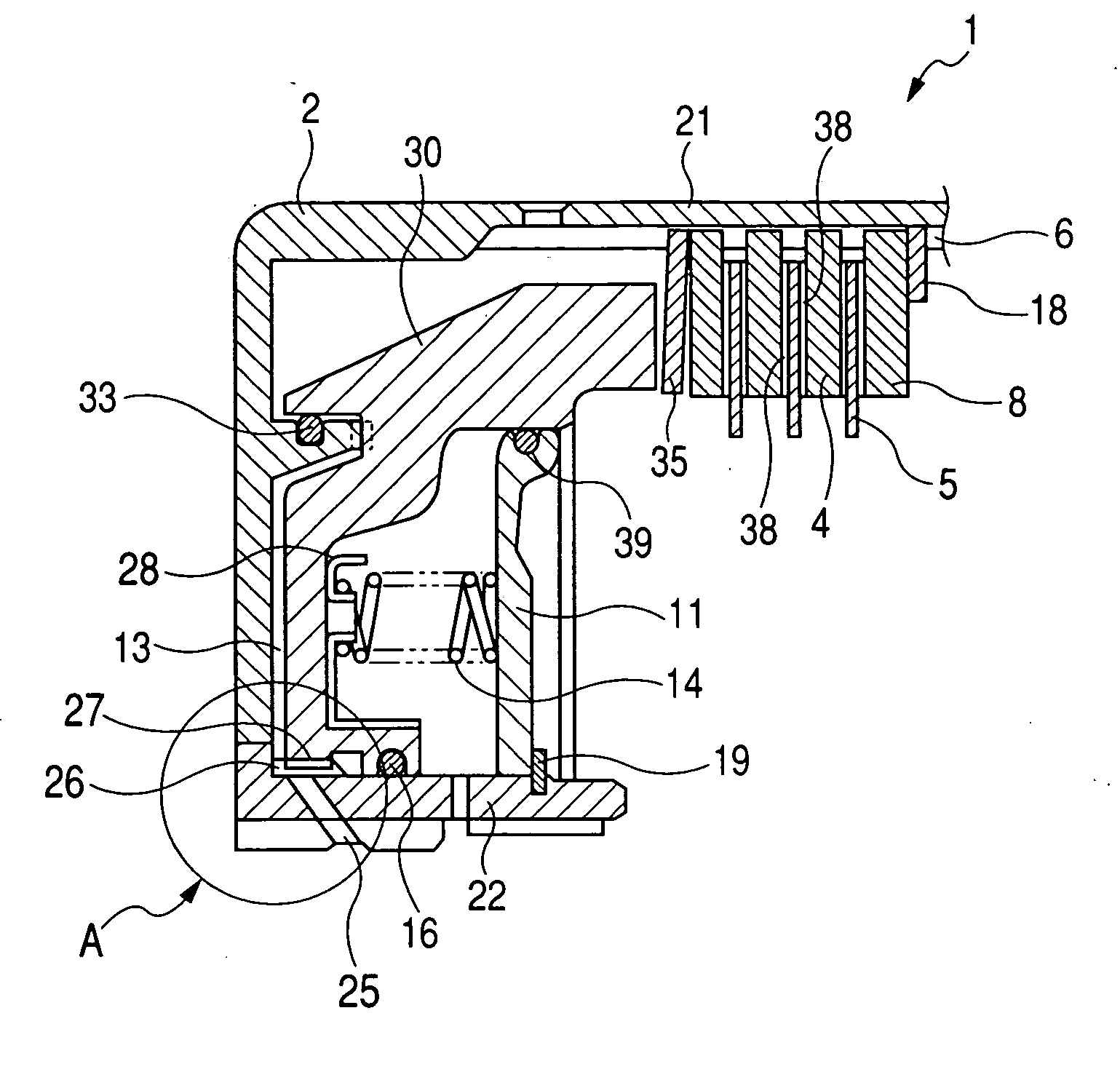
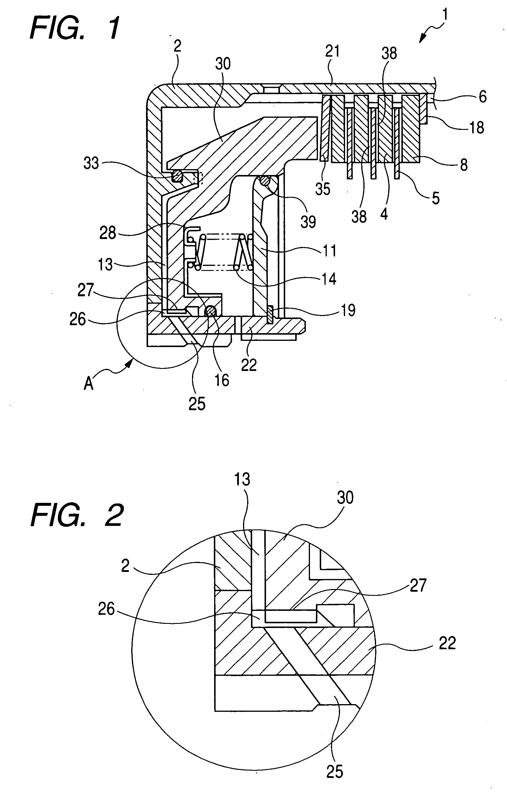
[0021]FIG. 1 is an axial sectional view showing a wet type multi-plate clutch 1 according to an embodiment of the present invention, and FIG. 2 is an enlarged view of a portion shown by a circle A in FIG. 1.

[0022] In the wet type multi-plate clutch 1, a clutch housing 2 and a hub (not shown) are arranged on a common axis. A spline 6 is formed in an inner peripheral surface of an outer cylindrical portion of the clutch housing 2 and separator plates 4 as first friction engaging elements are received in the spline, ...


PUM


Abstract

The present invention provides a wet type multi-plate clutch comprising a first friction engaging element coaxially arranged within a clutch housing, a second friction engaging element alternately disposed with the first friction engaging element, and a piston for applying an axial load to engage the first and second friction engaging elements with each other and wherein a projection is provided on an outer periphery of an inner diameter portion of the clutch housing or on an inner periphery of the piston and a recessed portion is provided in the inner periphery of the piston or in the outer periphery of the inner diameter portion of the clutch housing so that a relative rotation between the clutch housing and the piston is prevented by engaging the projection with the recessed portion.

Description

BACKGROUND OF THE INVENTION [0001] 1. Field of the Invention [0002] The present invention relates to a wet type multi-plate clutch used in an automatic transmission of a vehicle and the like. More particularly, the present invention relates to a wet type multi-plate clutch including means for preventing a relative rotation between a clutch housing and a piston. [0003] 2. Related Background Art [0004] In a wet type multi-plate clutch, a power is transmitted by engaging a plurality of friction engaging elements disposed within a clutch housing with each other. In order to apply an axial urging force to the friction engaging elements, a piston shiftable in an axial direction is provided within the clutch housing. [0005] The piston is shifted in the axial direction by supplying oil pressure into an oil pressure chamber defined between the piston and the clutch housing, thereby tightening or engaging the friction engaging elements. In order to maintain the oil pressure chamber in a liqui...

Claims


Application Information

Patent Timeline
Patent Type & Authority Applications(United States)
IPC IPC(8): F16D25/0638
CPCF16D25/0638
Inventor EGAWA, YOSHIHISA
Owner NSK WARNER
Why Eureka
Try Eureka