Audio signal processing method, audio signal processing apparatus, Hi-Fi video apparatus, digital video apparatus and 8 mm video apparatus

a digital video and audio signal technology, applied in the direction of digital signal error detection/correction, recording on magnetic tapes, instruments, etc., can solve the problems of frequency filter distorting the normal signal portion, noise generation everywhere, and pulse noise generated at the time of high-speed reproduction of a digital video apparatus, so as to reduce incongruity and noise reduction. , the effect of high quality

Inactive Publication Date: 2005-09-01
SONY CORP
View PDF4 Cites 2 Cited by
  • Summary
  • Abstract
  • Description
  • Claims
  • Application Information

AI Technical Summary

Benefits of technology

[0032] An object of the present invention is to provide an audio signal processing method and apparatus for eliminating shot noise and smoothly interpolating discontinuity of an audio signal without distorting a normal portion and thereby reducing the incongruity in sound and apparatuses using the same.
[0033] Another object of the present invention is to provide a method an apparatus for processing a reproduced audio signal to an audio signal free from incongruity in sound at the time of high speed reproduction in a magnetic tape type audio signal reproducing apparatus reproducing an audio signal recorded by helical scanning of a rotary audio head on a magnetic tape such as a Hi-Fi video apparatus, digital video signal recording and / or reproducing apparatus, and 8 mm video apparatus and such apparatuses using the same.
[0034] Still another object of the present invention is to provide a method and apparatus for processing a reproduced audio signal to an audio signal free from incongruity in sound at the time of high speed reproduction in a rotary audio signal reproducing apparatus reproducing an audio signal recorded on a substantially randomly accessable rotary recording medium such as a magnetic disk, optical disk, and opto-magnetic disk and such apparatuses using the same.

Problems solved by technology

Such noise is generated everywhere due to, for example, noise generated in the air or in the apparatus, scratches or dust on the magnetic tape, scratches or dust on the optical disk, scratches or dust on an analog record disk, and reading error of the reproducing apparatus.
Such noise causes a remarkably incongruity in sound.
However, a frequency filter distorts the normal signal portion as well and further is not that effective in elimination of short time and wide frequency band signals such as shot noise and discontinuity.
Further, prevalue hold and mean value interpolation are problematic in that a discontinuity newly occurs with the preceding and following data, so incongruity in sound is newly caused.
The reason for this is that, as shown in FIG. 4, at the time of special reproduction, the rotary head scans a plurality of Hi-Fi tracks by obliquely traversing them (helically scans them), so the video signal can be reproduced as one image by combining a plurality of fields, but, in contrast, noise due to discontinuity of the scanning of the rotary head frequently occurs in the audio signal to cause remarkable incongruity in sound, so the Hi-Fi track cannot be used.
However, when trying to save time while fully viewing and listening to the content by reproduction at a slightly high speed, for example, a 1.2× speed, the quality of sound when reproducing the audio signal recorded on the fixed audio track, which is fixed to such high speed reproduction, is insufficient.
However, the discontinuity of the audio signal occurring due to the tracks not being read at the time of high speed reproduction causes a remarkable incongruity in sound at the time of reproduction in the same way as the case of a Hi-Fi video apparatus.
With the methods of (1) and (2), however, discontinuity or muting periodically occurs, so the incongruity cannot be solved.
With the method of (3), the apparatus becomes complex and further the data becomes too large, so time compression and sampling rate conversion are necessary.
As a result, a new incongruity in sound such as a rise in sound pitch is caused.
Accordingly, there is a problem of how to repair the audio signal without incongruity.
With the method of (5), although the discontinuity is solved by a cross fading of the data before and after the discontinuity, this is done without considering waveform periodicity etc., so there is a problem in that incongruity due to mismatch of phase is newly caused.
An 8 mm video apparatus recording and reproducing an audio signal by a rotary head suffers from problems similar to those described above.
However, a certain time is required for reading data.
Therefore, at the time of high speed reproduction, it is sometimes necessary to deliberately reduce the number of read fields.
At this time, the problem of discontinuity of sound similar to the above arises.

Method used


Image

  • Audio signal processing method, audio signal processing apparatus, Hi-Fi video apparatus, digital video apparatus and 8 mm video apparatus
  • Audio signal processing method, audio signal processing apparatus, Hi-Fi video apparatus, digital video apparatus and 8 mm video apparatus
  • Audio signal processing method, audio signal processing apparatus, Hi-Fi video apparatus, digital video apparatus and 8 mm video apparatus

Examples


first embodiment

[0128] The waveform connector 15 of the first embodiment of the audio signal processing method of the present invention will be explained by referring to FIG. 9 to FIG. 11 and FIG. 12 to FIG. 18.

[0129]FIG. 9 is a view of the configuration of the waveform connector 15.

[0130]FIG. 10 is a view of the processing of the signal buffer 152.

[0131]FIG. 11 is a flow chart of the processing of a signal processor 155.

[0132]FIG. 12 to FIG. 18 are views of the waveforms of the signals processed at the waveform connector.

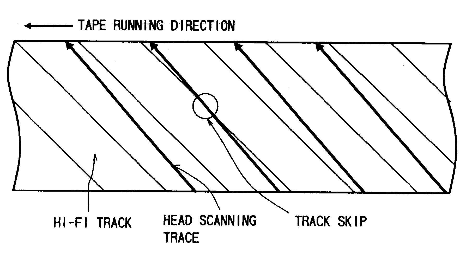
[0133] The waveform connector 15 is a waveform connector utilizing the track skip pulse S13 generated in the track skip detector 13. The track skip time becomes clear from the track skip pulse S13, so the waveform connector 15 connects the waveform by utilizing this.

[0134] The waveform connector 15 illustrated in FIG. 9 has an A / D converter 151, a signal buffer 152, a D / A converter 154, and a signal processor 155.

[0135] When the audio signal is input in a digital format, th...


PUM

PropertyMeasurementUnit
angleaaaaaaaaaa
Nyquist frequencyaaaaaaaaaa
timeaaaaaaaaaa

Abstract

An audio signal processing method for repairing an anomalous state such as noise, a discontinuity, and a break of sound, comprising detecting the anomalous state of an audio signal, deleting the audio signal in the anomalous segment, deducing the correct audio signal by referring to the waveform of the audio signal before and after the deleted segment, generating a repair signal for repairing the signal in the deleted segment based on the deduced result, inserting the repair signal into the deleted segment, and connecting it to the audio signal before and after the deleted segment.

Description

BACKGROUND OF THE INVENTION [0001] 1. Field of the Invention [0002] The present invention relates to a method and apparatus for processing an audio signal and apparatuses using the same. More particularly, the present invention relates to a method an apparatus for eliminating shot noise, discontinuity, and a data loss and repairing an audio signal and apparatuses using the same. [0003] The present invention is applied to compensation for loss of sound occurring when performing high speed reproduction (special reproduction) etc. in a receiver of a broadcasted audio signal, a reproduction system of an audio signal recorded on a magnetic tape, an optical disk, an opto-magnetic disk, or the like, and a decoding system of a digitally transmitted audio signal, for example, a Hi-Fi video apparatus, a digital video apparatus (digital video signal recording and / or reproducing apparatus), and an 8 mm video apparatus. [0004] 2. Description of the Related Art [0005] In a receiver of a broadcast...

Claims


Application Information

Patent Timeline
Patent Type & Authority Applications(United States)
IPC IPC(8): G11B5/008G11B5/53G11B20/10G11B20/12G11B20/18H04N5/782H04N5/7826H04N5/783H04N9/806H04N19/89
CPCG11B5/0086G11B5/531G11B15/026G11B15/125G11B15/1875G11B20/10527H04N9/8063G11B20/18G11B20/1876G11B2020/10546H04N5/78213H04N5/78263H04N5/783G11B20/1201
Inventor ABE, MOTOTSUGUINOUE, AKIRAMATSUMOTO, JUNSUGINUMA, KOJINISHIGUCHI, MASAYUKI
Owner SONY CORP
Why Eureka
Try Eureka