Zoom lens system and imaging apparatus having the same

a technology of zoom lens and imaging apparatus, applied in the direction of optics, instruments, diffraction gratings, etc., can solve the problems of insufficient back focal distance, difficult to solve the problems of 1 and 2, obscure images, etc., and achieve excellent optical performance and excellent images.

Inactive Publication Date: 2005-09-01
CANON KK
View PDF9 Cites 27 Cited by
  • Summary
  • Abstract
  • Description
  • Claims
  • Application Information

AI Technical Summary

Benefits of technology

[0018] The present invention is directed to a zoom lens system capable of maintaining excellent optical performance over the entire zooming region even with a high zoom rat

Problems solved by technology

As is well known, if a large amount of decentration aberration is produced when the image stabilizing lens unit is decentered, images become obscure when the image deflection is corrected.
However, in a zoom lens with a high zoom ratio in which the focal distance at the telephoto end is large, solving Problems 1 and 2 has been difficult at the zooming position of the telephoto end.
When the zoom lens disclosed in Japanese Patent Laid-Open No. 2-35406 is applied to an interchangeable lens of single lens reflex cameras, the back focal distance may be insufficient for securing the driving space of a QR mirror (quick return mirror).
The zoom lens disclosed in Japanese Patent Laid-Open No. 8

Method used


Image

  • Zoom lens system and imaging apparatus having the same
  • Zoom lens system and imaging apparatus having the same
  • Zoom lens system and imaging apparatus having the same

Examples


Embodiment Construction

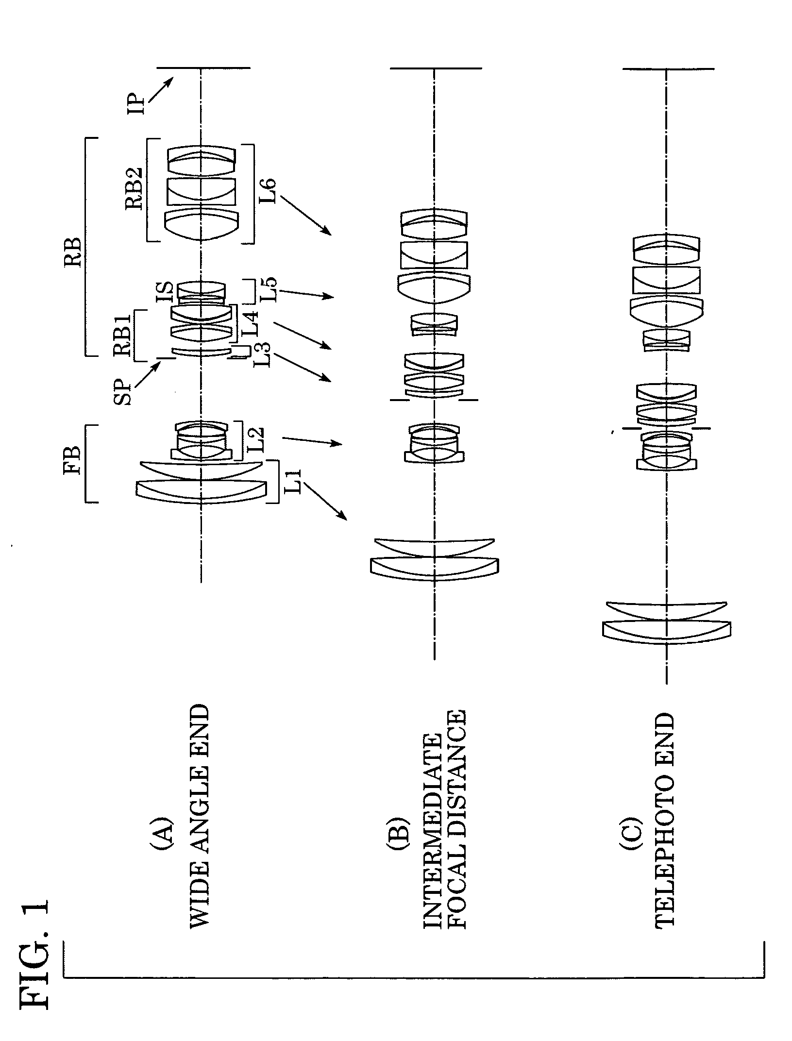
[0058] Embodiments of a zoom lens system according to the present invention will be described below with reference to the drawings.

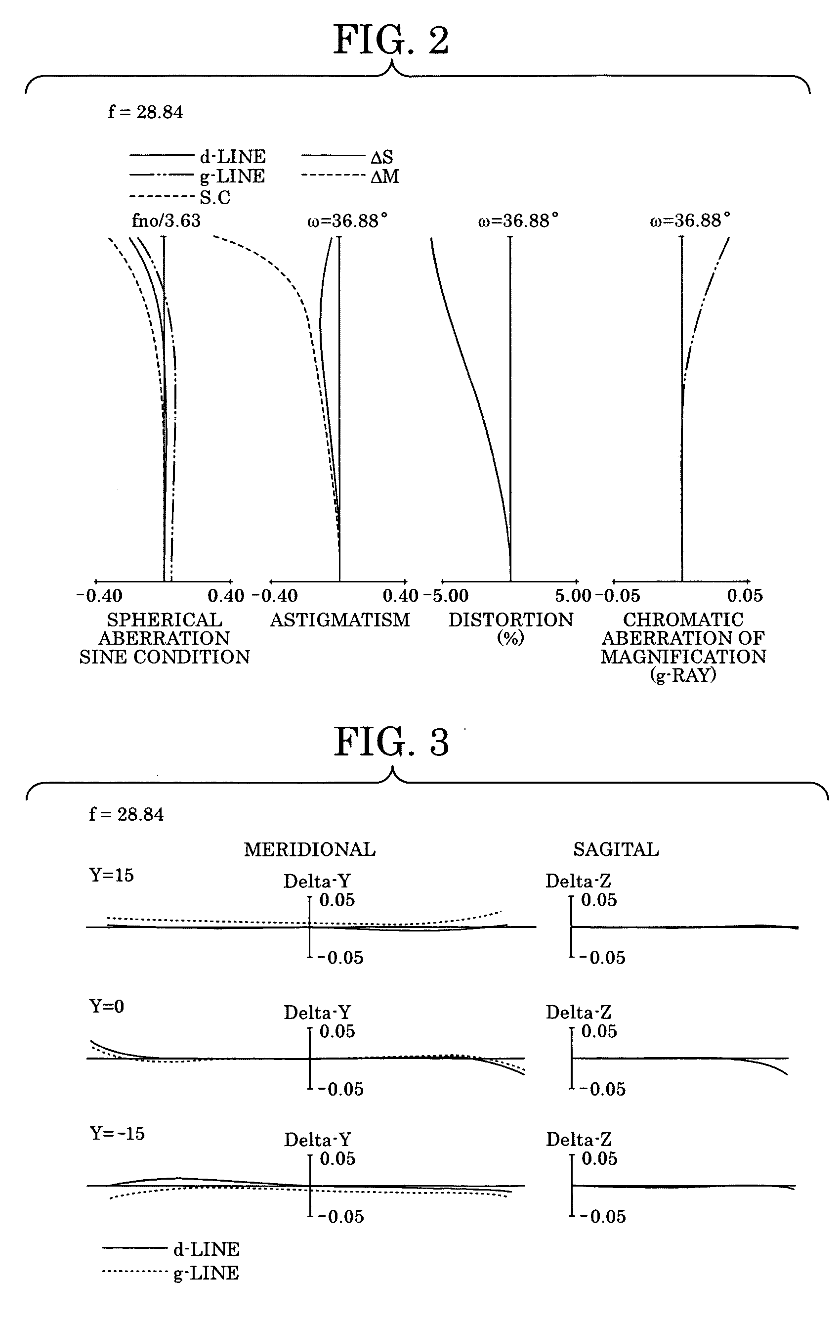
[0059]FIG. 1 shows schematic drawings of a zoom lens according to a first embodiment of the present invention; FIG. 2 is a longitudinal aberration diagram of the zoom lens according to the first embodiment at the wide angle end under base conditions (the object is located at an infinite distance and the image stabilizing lens unit is not deflected in a direction perpendicular to an optical axis); and FIG. 3 is a lateral aberration diagram of the zoom lens according to the first embodiment at the wide angle end under vibration-proof conditions (the image position of the object at an infinite distance is displaced by an angle equivalent to a field angle of 0.3°).

[0060]FIG. 4 is a longitudinal aberration diagram of the zoom lens according to the first embodiment at an intermediate zoom position under the base conditions; FIG. 5 is a lateral aberration dia...


PUM


Abstract

A zoom lens system includes a front lens group and a rear lens group arranged from an object side to an image side in that order. The front lens group includes a plurality of lens units, and during zooming from a wide angle end to a telephoto end, imaging magnification is increased by changing spaces between the plurality of lens units. The rear lens group with positive optical power as a whole includes a lens unit IS with negative optical power being movable so as to have a component in a direction perpendicular to an optical axis, and a lens component RB2 with positive optical power disposed on the image side with respect to the lens unit IS. A space between the lens unit IS and the lens component RB2 is changed during zooming. The following condition is established to satisfy:
0.05<|fis|/ft<0.25,
wherein (fis) denotes a focal distance of the lens unit IS, and (ft) denotes a focal distance at the telephoto end of the zooming lens system.

Description

BACKGROUND OF THE INVENTION [0001] 1. Field of the Invention [0002] The present invention relates to a zoom lens system and an image pickup system having the zoom lens system, and in particular relates to a zoom lens system in which picked-up images are stabilized by optically correcting image deflection produced when the zoom lens system is vibrated (inclined). The zoom lens system according to the present invention is suitable for an imaging optical system, such as a silver-film camera, a video camera, and a digital still camera. [0003] 2. Description of the Related Art [0004] If vibration is incidentally transmitted to an imaging system, image deflection is produced in picked-up images. Various zoom lenses having a mechanism to compensate for the image deflection due to the incidental vibration (image stabilizer) have been proposed. For example, an optical system is known in which part of a lens unit constituting an optical system (zoom lens) is moved in a direction substantially...

Claims


Application Information

Patent Timeline
IPC IPC(8): G02B13/18G02B15/173G02B15/20G02B27/64
CPCG02B27/646G02B15/173
Inventor MISAKA, MAKOTO
Owner CANON KK
Why Eureka
Try Eureka