Self-pinned spin valve sensor with stress modification layers for reducing the likelihood of amplitude flip
a self-pinned, spin valve technology, applied in the direction of magnetic recording heads, instruments, data recording, etc., can solve the problems of pinning field to flip its orientation, corrupt data, etc., and achieve the effect of reducing the likelihood
- Summary
- Abstract
- Description
- Claims
- Application Information
AI Technical Summary
Benefits of technology
Problems solved by technology
Method used
Image
Examples
first embodiment
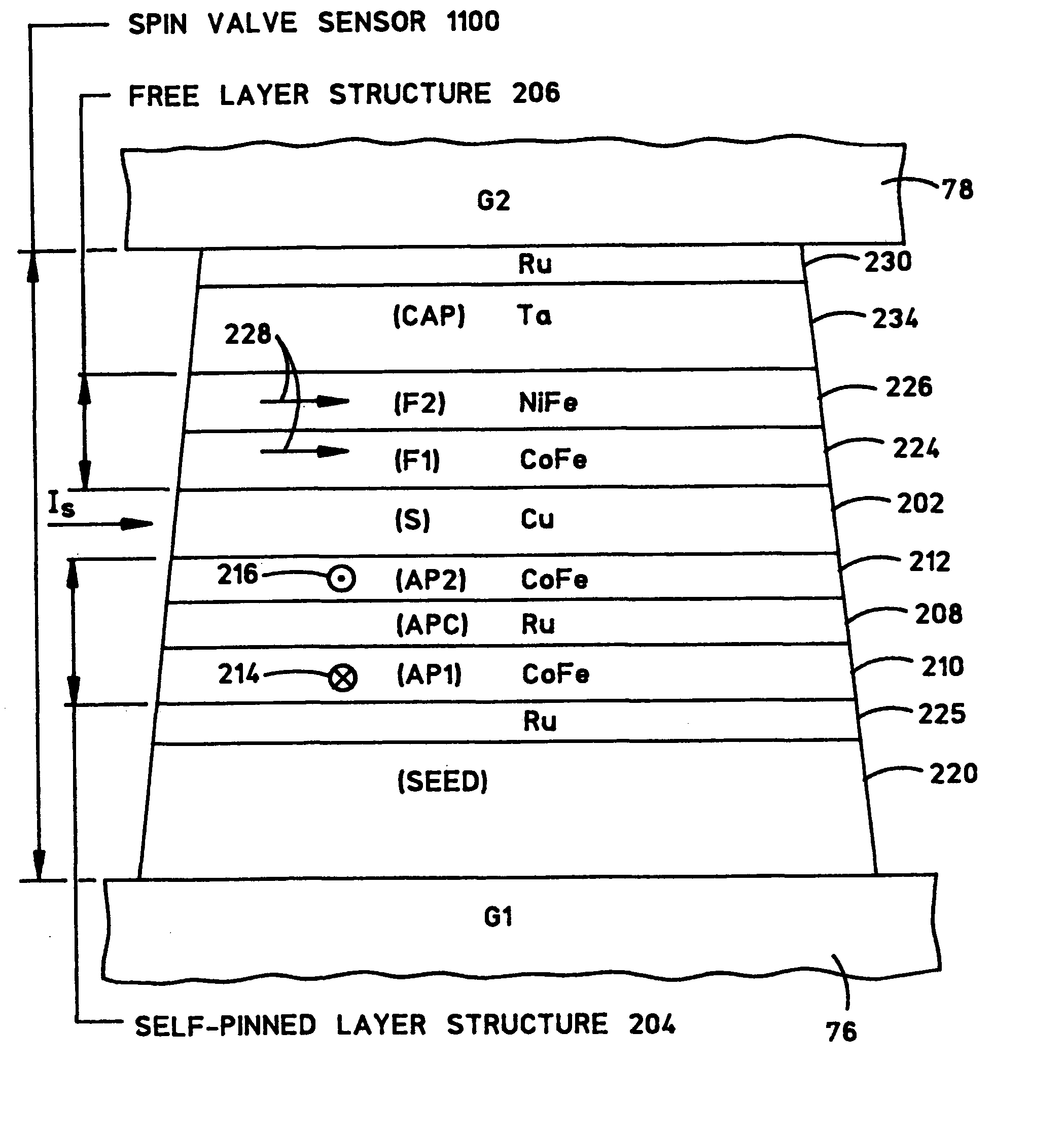
[0040]FIG. 11 is an ABS illustration of a multi-layer structure of a spin valve sensor 1200 of the self-pinned type with compressive stress modification layers for reducing the likelihood that the pinning field will flip its direction. Spin valve sensor 1100 of FIG. 11 is similar to the spin valve sensor of FIG. 10 except that it includes compressive stress modification layers 225 and 230.
[0041] Compressive stress modification layer 225 is formed adjacent AP self-pinned layer structure 204. More particularly, compressive stress modification layer 225 is formed directly between first AP pinned layer 210 and seed layer 220. The addition of compressive stress modification layer 225 modifies the intrinsic compressive stress within spin valve sensor 1100. Since the self-pinning effect is a result of negative anisotropy which is based on positive magnetostriction and compressive stress, any external compressive stresses have a diminished effect on the pinning field. Therefore, compressive...
second embodiment
[0044]FIG. 12 is an ABS illustration of a multi-layer structure of a spin valve sensor 1200 of the self-pinned type with compressive stress modification layers for reducing the likelihood that the pinning field will flip its direction. Spin valve sensor 1200 is similar to the spin valve sensor of FIG. 11 except that compressive stress modification layer 230 of FIG. 12 is formed between capping layer 234 and free layer structure 206 instead of being formed on top of capping layer 234. As with compressive stress modification layer 230 of FIG. 11, compressive stress modification layer 230 of FIG. 12 modifies the intrinsic compressive stress within spin valve sensor 1200 and therefore reduces the likelihood that the pinning field will flip its direction. Although the structure of spin valve sensor 1200 of FIG. 12 may be well-suited for some applications, spin valve sensor 1100 of FIG. 11 is preferred over that of FIG. 12 since, in some GMR designs, the presence of ruthenium next to the ...
third embodiment
[0045]FIG. 13 is an ABS illustration of a multi-layer structure of a spin valve sensor 1300 of the self-pinned type having a compressive stress modification layer for reducing the likelihood that the pinning field will flip its direction. Spin valve sensor 1300 is similar to the spin valve sensor of FIG. 11 except that compressive stress modification layer 225 of FIG. 11 is removed. Nevertheless, compressive stress modification layer 230 of FIG. 13 formed over capping layer 234 in itself modifies the intrinsic compressive stress within spin valve sensor 1300 and therefore reduces the likelihood that the pinning field will flip its direction.
PUM
| Property | Measurement | Unit |
|---|---|---|
| thick | aaaaa | aaaaa |
| Thicknesses | aaaaa | aaaaa |
| Thicknesses | aaaaa | aaaaa |
Abstract
Description
Claims
Application Information
 - R&D
- Intellectual Property
- Life Sciences
- Materials
- Tech Scout
- Unparalleled Data Quality
- Higher Quality Content
- 60% Fewer Hallucinations
Browse by: Latest US Patents, China's latest patents, Technical Efficacy Thesaurus, Application Domain, Technology Topic, Popular Technical Reports.
© 2025 PatSnap. All rights reserved.Legal|Privacy policy|Modern Slavery Act Transparency Statement|Sitemap|About US| Contact US: help@patsnap.com


