
Status flags in a system of electronic pyrotechnic devices such as electronic detonators

Inactive Publication Date: 2005-09-01
SPECIAL DEVICES
View PDF15 Cites 10 Cited by
  • Summary
  • Abstract
  • Description
  • Claims
  • Application Information

AI Technical Summary

Benefits of technology

[0005] The present invention thus may be used to effect more efficient and / or safe management of the firing process within the electronic detonator blasting system, and / or a more reliably successful firing sequence.

Problems solved by technology

But if the status is not checked, the next process or event in the firing sequence may be futile or faulty.
For example, if the firing capacitor has not been properly charged and armed, issuing a fire command will not result in a successful firing.
Moreover, if all detonators have not been calibrated and synchronized properly with respect to a central unit timing, the relative firing delay of each detonator may be compromised.
Status flags have been used in other fields such as in digital machines for register bookkeeping, however, heretofore status flags have not been applied to electronic blasting systems or electronic detonators.

Method used


Image

  • Status flags in a system of electronic pyrotechnic devices such as electronic detonators
  • Status flags in a system of electronic pyrotechnic devices such as electronic detonators
  • Status flags in a system of electronic pyrotechnic devices such as electronic detonators

Examples


Embodiment Construction

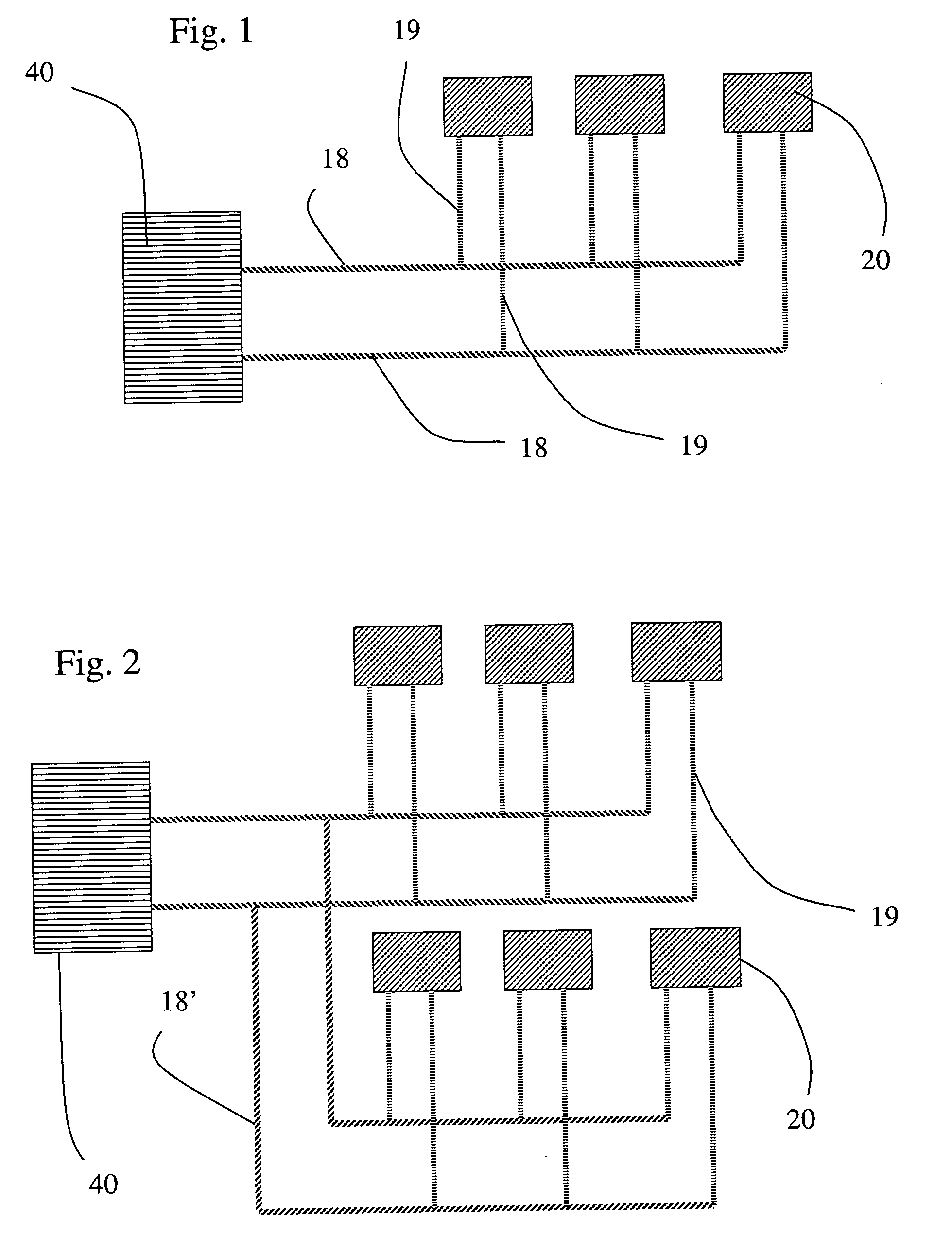
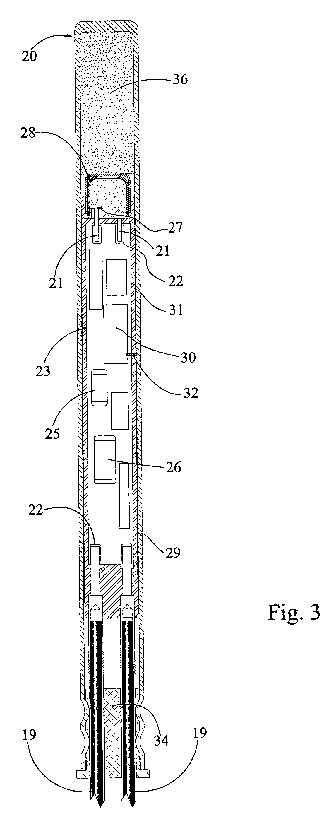
[0020] To describe the present invention with reference to the details of a particular preferred embodiment, it is noted that the present invention may be employed in an electronic system comprising a network of slave devices, for example, an electronic blasting system in which the slave devices are electronic detonators. As depicted in FIG. 1, one embodiment of such an electronic blasting system may comprise a number of detonators 20, a two-line bus 18, leg wires 19 including connectors for attaching the detonator to the bus 18, a logger (not shown), and a blasting machine 40. The detonators 20 are preferably connected to the blasting machine 40 in parallel (as in FIG. 1) or in other arrangements including branch (as in FIG. 2), tree, star, or multiple parallel connections. A preferred embodiment of such an electronic blasting system is described below, although it will be readily appreciated by one of ordinary skill in the art that other systems or devices could also be used, and ...


PUM


Abstract

An electronic blasting system in which each detonator is provided with status flags or the like to convey the status of various states or conditions of the detonator such as detection on the system bus, firing capacitor charging, calibration of the detonator's circuitry, and events such as the successful receipt of a fire command.

Description

BACKGROUND OF THE INVENTION [0001] The present invention is directed generally to a system of electronic pyrotechnic devices such as electronic detonators, and more particularly, to the use of status flags in such systems and devices. [0002] Prior art detonating systems have employed electronic detonators that fire in response to an excitation signal from a blasting machine, without first checking the status of detection on the bus, charging, and calibration of the detonators. For example, U.S. Pat. No. 5,363,765, entitled “Electronic Delay Circuit for Firing Ignition Element,” issued to Aikou et al., describes an electronic detonator that fires upon counting a predetermined number of clock pulses without checking for the charge status of the firing capacitor. But if the status is not checked, the next process or event in the firing sequence may be futile or faulty. For example, if the firing capacitor has not been properly charged and armed, issuing a fire command will not result i...

Claims


Application Information

Patent Timeline
IPC IPC(8): F42D1/055
CPCF42D1/055
Inventor JENNINGS, DAVID T. III
Owner SPECIAL DEVICES
Learn More