Case for handheld device

a handheld device and case technology, applied in the direction of portable casings, electrical apparatus, cabinet/cabinet/drawer, etc., can solve the problems of slipping of handheld devices, tearing loose from the case, and first removing the handheld devi

Inactive Publication Date: 2005-09-01
CHEE BILL TSANG CHUN
View PDF23 Cites 9 Cited by
  • Summary
  • Abstract
  • Description
  • Claims
  • Application Information

AI Technical Summary

Benefits of technology

[0010] For the reasons cited above, it is an object of the present invention to provide a device case that securely holds a handheld device even when the device case is open. It is a further object to provide such a case that allows operation of the handheld device while it is encased. It is a yet further object to provide such a device case that allows the encased handheld device to connect to a charging station without first being removed from the device case. It is a still yet further object to provide such a device case that safely and securely stores removable memory cards for easy retrieval.

Problems solved by technology

The disadvantage of conventional cases is that the handheld device must first be removed from the case in order to insert it into the charging station.
A disadvantage of such a strap is that it may tear loose from the case and allow slippage of the handheld device.
The disadvantage of this bracket is that it includes moving parts that may wear out or break and that also increase the cost of manufacturing.
A disadvantage of this case is that the electronic device is not securely attached to the case and can slide out of the case if the flap is open.
Another disadvantage is that the keypad of the handheld device is not exposed, thereby prohibiting the use of the device while it is in the case.
The disadvantage of this case is it includes a keyboard and an I / O port that is only suitable for certain types of PDAs.
Another disadvantage of this case is that it does not fully encase the handheld device, thereby exposing the device to damage.

Method used


Image

  • Case for handheld device
  • Case for handheld device
  • Case for handheld device

Examples


Embodiment Construction

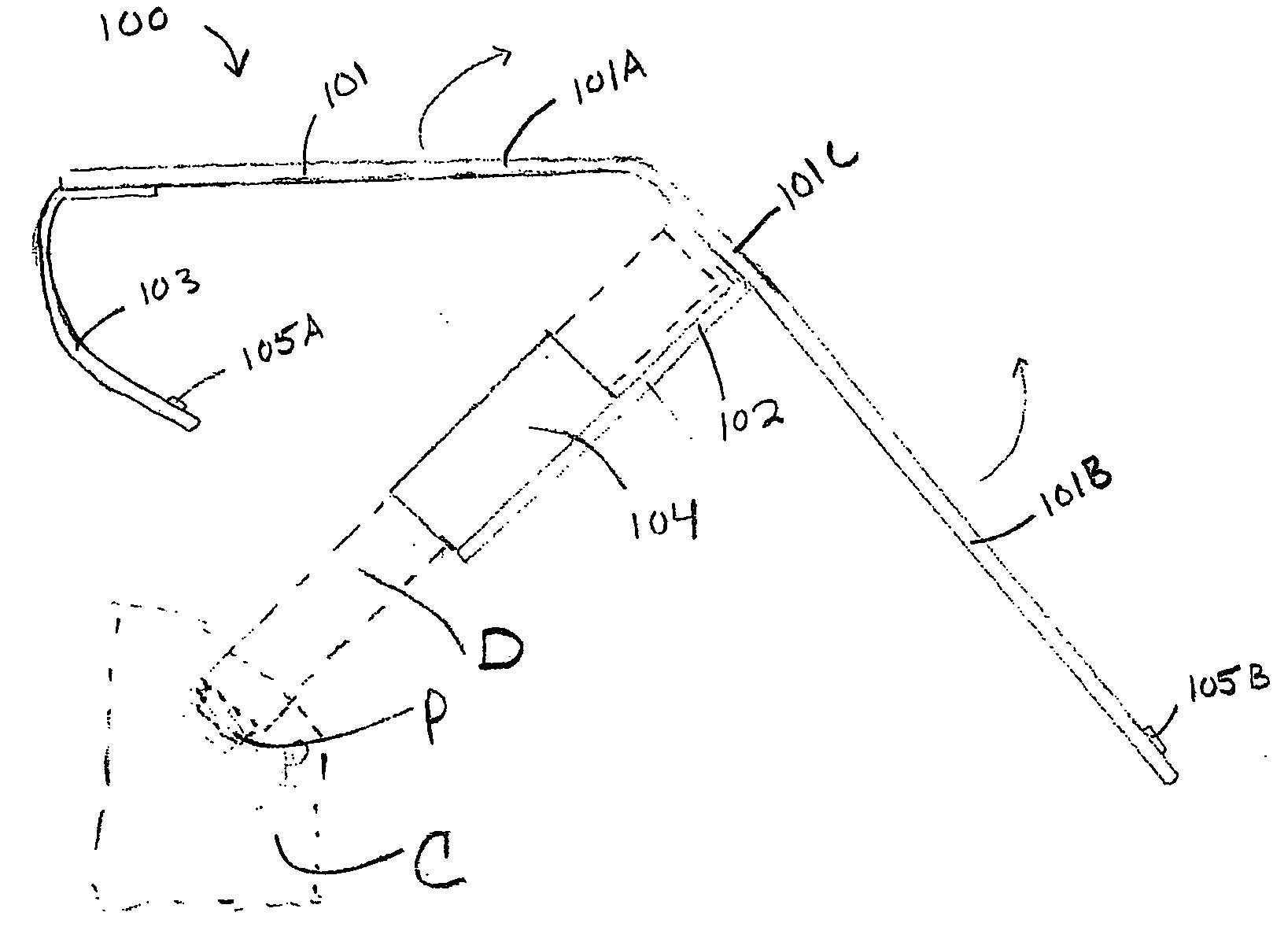
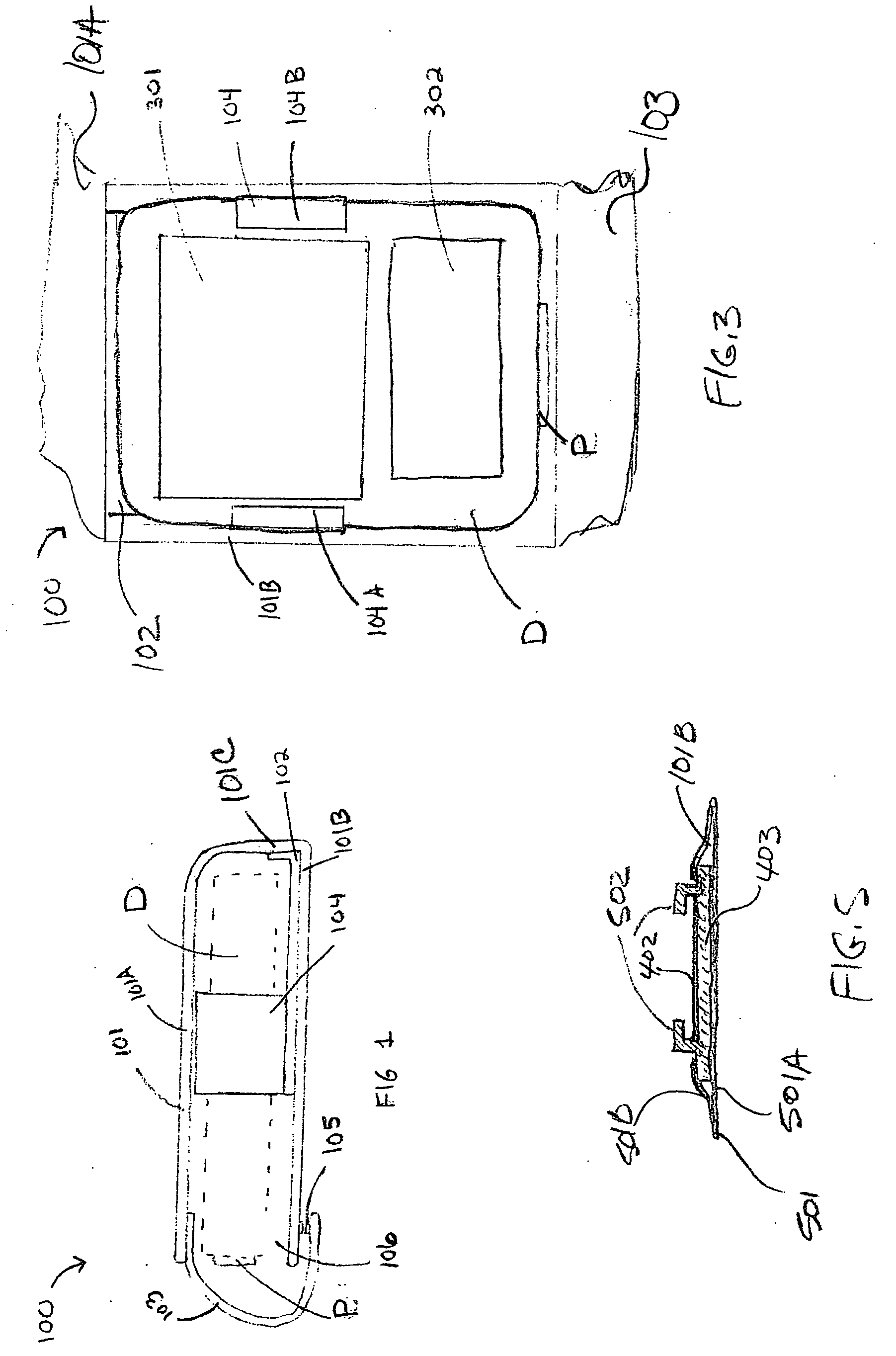
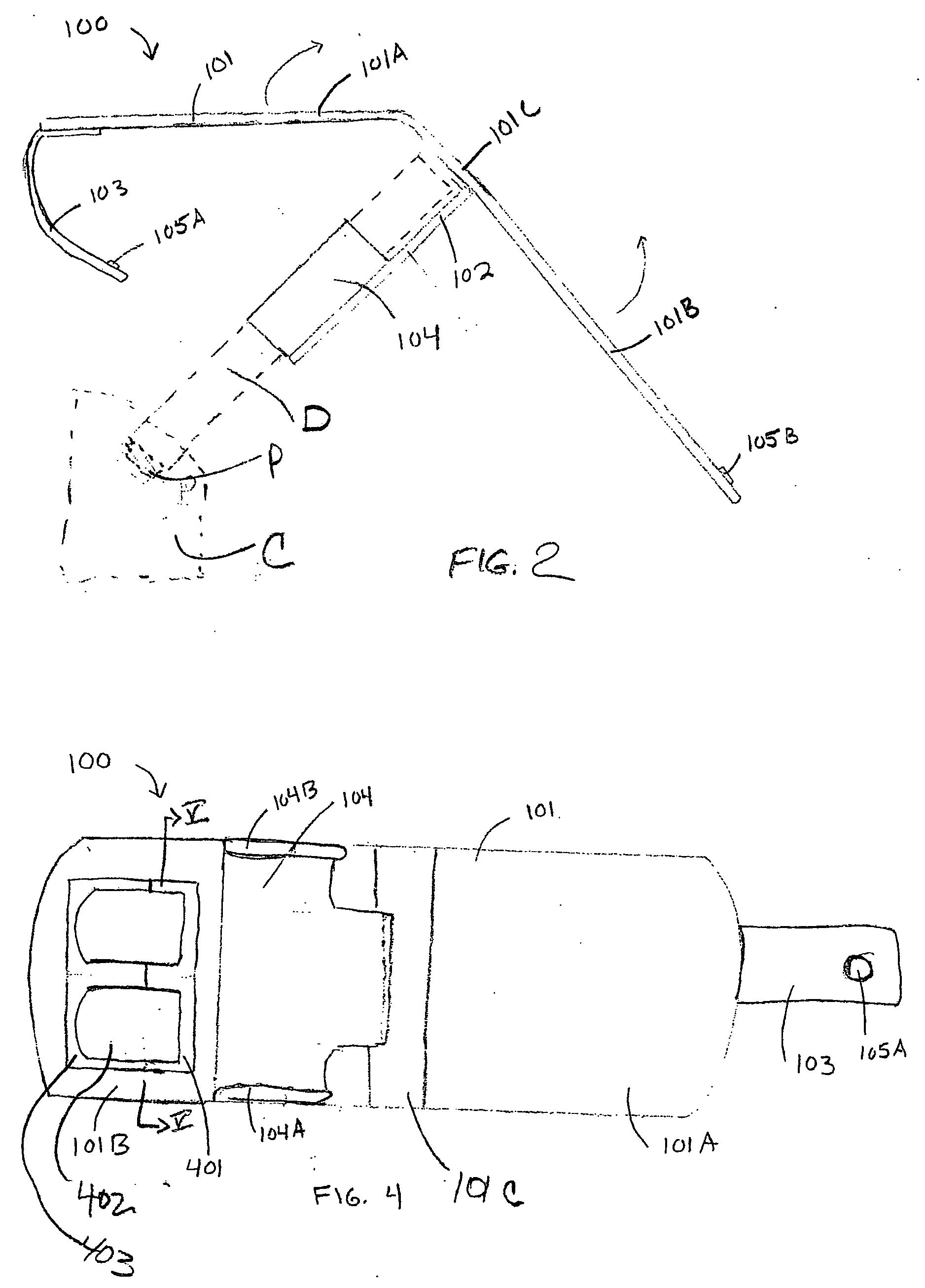
[0020]FIGS. 1 and 2 show a side view of a device case 100 according to the invention in a closed and an open state, respectively. The device case 100 comprises an open-sided case panel 101, having a device bracket 104 and a closure strap 103. The case panel 101 is a substantially flat bendable or foldable body having a first panel 101A, a second panel 101B and an intermediate panel 101C. The case panel 101 folds closed forming a cavity 106 that provides space for a handheld device D. The closure strap 103 is fixedly attached to the first panel 101A and is provided with a closure means 105 that secures the first panel 101A to the second panel 101B. The device bracket 104 is attached to the intermediate panel 101C. In the embodiment shown, the device bracket 104 is integrated with a device bracket strap 102 that is pivotably attached at one end to the intermediate panel 101C, with the device bracket 104 at the other end. The device bracket 104 is shaped to receive and securely hold th...


PUM


Abstract

A case that securely holds a handheld device and allows for charging the device while it is held in the case. The case includes a two-fold panel that folds on itself to form a cavity for receiving the handheld device. A device bracket for holding the handheld device is attached to a strap that is movably affixed to the inside of the case and holds the handheld device without covering the display and keypad areas. The portions of the case that cover the front and back surfaces of the handheld device fold back, away from the device bracket, thereby freeing up the end of the handheld device with the charging connector so that it may be inserted into a charging station.

Description

BACKGROUND INFORMATION [0001] 1. Field of the Invention [0002] The invention relates to the field of cases for small, handheld devices, such as PDAs, MP3 players and other devices. More particularly, the invention relates to a case that allows the handheld device to be connected to a synchronization or charging station without first removing it from the case. [0003] 2. Description of the Prior Art [0004] Handheld devices are ubiquitous today. Typically, such handheld devices have a connector at one end for charging the rechargeable battery in the device. To recharge the device, it is inserted into a docking or charging station. Many types of cases for holding such handheld devices are known. The cases typically enclose all sides of the handheld device. The disadvantage of conventional cases is that the handheld device must first be removed from the case in order to insert it into the charging station. [0005] Cases that include a means of attaching the handheld device to the case wit...

Claims


Application Information

Patent Timeline
Patent Type & Authority Applications(United States)
IPC IPC(8): H01Q1/24H04B1/38H05K5/00H05K5/04H05K5/06
CPCH05K5/0086H04B1/3888
Inventor CHEE, BILL TSANG CHUN
Owner CHEE BILL TSANG CHUN
Why Eureka
Try Eureka