
Method for integrating heat conductor with heat dissipating fin

a heat conductor and heat dissipating fin technology, applied in the direction of tubular elements, lighting and heating apparatus, metal-working apparatus, etc., can solve the problems of increasing thermal resistance, affecting the outside appearance, and the heat tube cannot pass the aperture on each heat dissipating fin very smoothly

Inactive Publication Date: 2005-09-08
CPUMATE INC
View PDF0 Cites 0 Cited by
  • Summary
  • Abstract
  • Description
  • Claims
  • Application Information

AI Technical Summary

Benefits of technology

[0016] In accordance with the present invention, the aperture on the heat dissipating fin has an inside diameter larger than or equal to an outer diameter of the heat conductor so that the heat conductor can easily pass through the aperture of the heat dissipating fin to be combined therewith.

Problems solved by technology

However, since the foresaid heat-conducting medium is usually viscose-like, the heat tube can not pass the aperture on each heat dissipating fin very smoothly when the heat-conducting medium is spread on the heat tube.
Besides, the extra viscose-like heat-conducting medium would spill from each aperture, which not only affects the outside appearance, but also increases the thermal resistance when the impurities are attached thereon.
On the other hand, if the coated heat-conducting medium is not enough, the heat tube would not be able to be contacted with the aperture on each heat dissipating fin tightly.
Therefore, it is very hard to accurately control the amount of the coated heat-conducting medium or to evenly spread the heat-conducting medium on the heat tube during the integrating process of the heat tube and the heat dissipating fin, and that seriously affects the product quality and results in plenty of manufacturing troubles.
In addition, there is another disadvantage, in which the aperture of the heat dissipating fin is designed to have a slightly smaller diameter than the outer diameter of the heat tube so that the heat dissipating fin can be directly pushed and put around the heat tube.
However, since the thickness of the tube wall is very thin (thinner than 0.5 mm), it is very common to cause a distortion by improperly extruding the heat tube or to impair the heat tube by accidentally scratching the surface of the heat tube.
Hence, how to improve the process for integrating the heat tube and the heat dissipating fin has become a major problem waited to be solved in the industry.

Method used


Image

  • Method for integrating heat conductor with heat dissipating fin
  • Method for integrating heat conductor with heat dissipating fin
  • Method for integrating heat conductor with heat dissipating fin

Examples


Embodiment Construction

[0030] The present invention will now be described more specifically with reference to the following embodiments. It is to be noted that the following descriptions of preferred embodiments of this invention are presented herein for purpose of illustration and description only; it is not intended to be exhaustive or to be limited to the precise form disclosed.

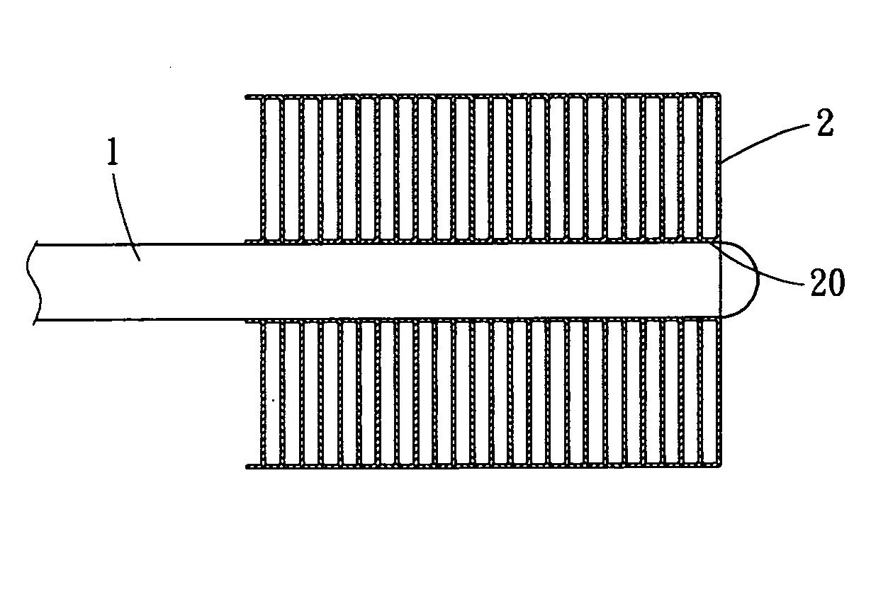
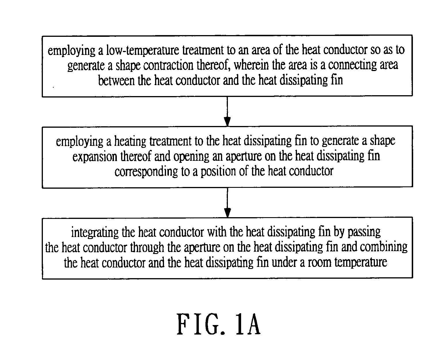
[0031] Please refer to FIGS. 1A and 2-4. FIG. 1A is a flow chart illustrating the steps for integrating a heat conductor with a heat dissipating fin according to the first preferred embodiment of the present invention. FIG. 2 is a diagram showing the heat conductor and the heat dissipating fin before combined. FIG. 3 is a diagram showing the heat tube and the heat dissipating fin after combined. FIG. 4 is a sectional diagram showing the heat dissipating device combined by the heat tube and a plurality of heat dissipating fin. A method for integrating a heat conductor with a heat dissipating fin is provided in the present invent...


PUM

PropertyMeasurementUnit
Temperatureaaaaaaaaaa
Diameteraaaaaaaaaa
Densityaaaaaaaaaa

Abstract

A method for integrating a heat conductor with a heat dissipating fin is provided. The steps includes: a) employing a low-temperature treatment to an area of the heat conductor so as to generate a shape contraction thereof, wherein the area is a connecting area between the heat conductor and the heat dissipating fin; b) employing a heating treatment to the heat dissipating fin to generate a shape expansion thereof and opening an aperture on the heat dissipating fin corresponding to a position of the heat conductor; and c) integrating the heat conductor with the heat dissipating fin by passing the heat conductor through the aperture on the heat dissipating fin and combining the heat conductor and the heat dissipating fin under a room temperature. Accordingly, the contact density between heat conductor and heat dissipating fin is increased, while the thermal resistance is reduced.

Description

BACKGROUND OF THE INVENTION [0001] The present invention is related to a method for integrating a heat conductor with a heat dissipating fin, and more particularly, to an integrating method employing a temperature change to the metal material to cause a physical change thereof for easily combining a heat conductor with a heat dissipating fin tightly. It has been a general trend to use a heat conductor as a heat dissipating element in the fields relevant to computers. By owning the properties including high heat-conducting ability, short heat-conducting time, high heat-conducting speed, light weight, simple structure, and multi-purpose, the heat conductors are very suitable for the heat dissipating needs of electronic products since they can conduct large amount of heat without consuming any electrical power, especially the heat conductors like heat tubes and copper pillars. [0002] In the past, when connecting or combining the heat tube of heat conductor with the heat dissipating fin...

Claims


Application Information

Patent Timeline
IPC IPC(8): F28F7/00
CPCF28F1/30Y10T29/49378F28F2275/12
Inventor LIN, KUO-LENTSUI, HUI-MIN
Owner CPUMATE INC
Learn More