
Gyrocompass

Active Publication Date: 2005-09-08
YOKOGAWA DENSIKIKI +1
View PDF6 Cites 18 Cited by
  • Summary
  • Abstract
  • Description
  • Claims
  • Application Information

AI Technical Summary

Benefits of technology

[0022] The object of the invention is to provide a gyrocompass which is capable of feeding electricity to a gyro rotor without using a harmful substance in the feeding route into a gyrosphere and realizing follow-up accuracy equivalent to conventional one.
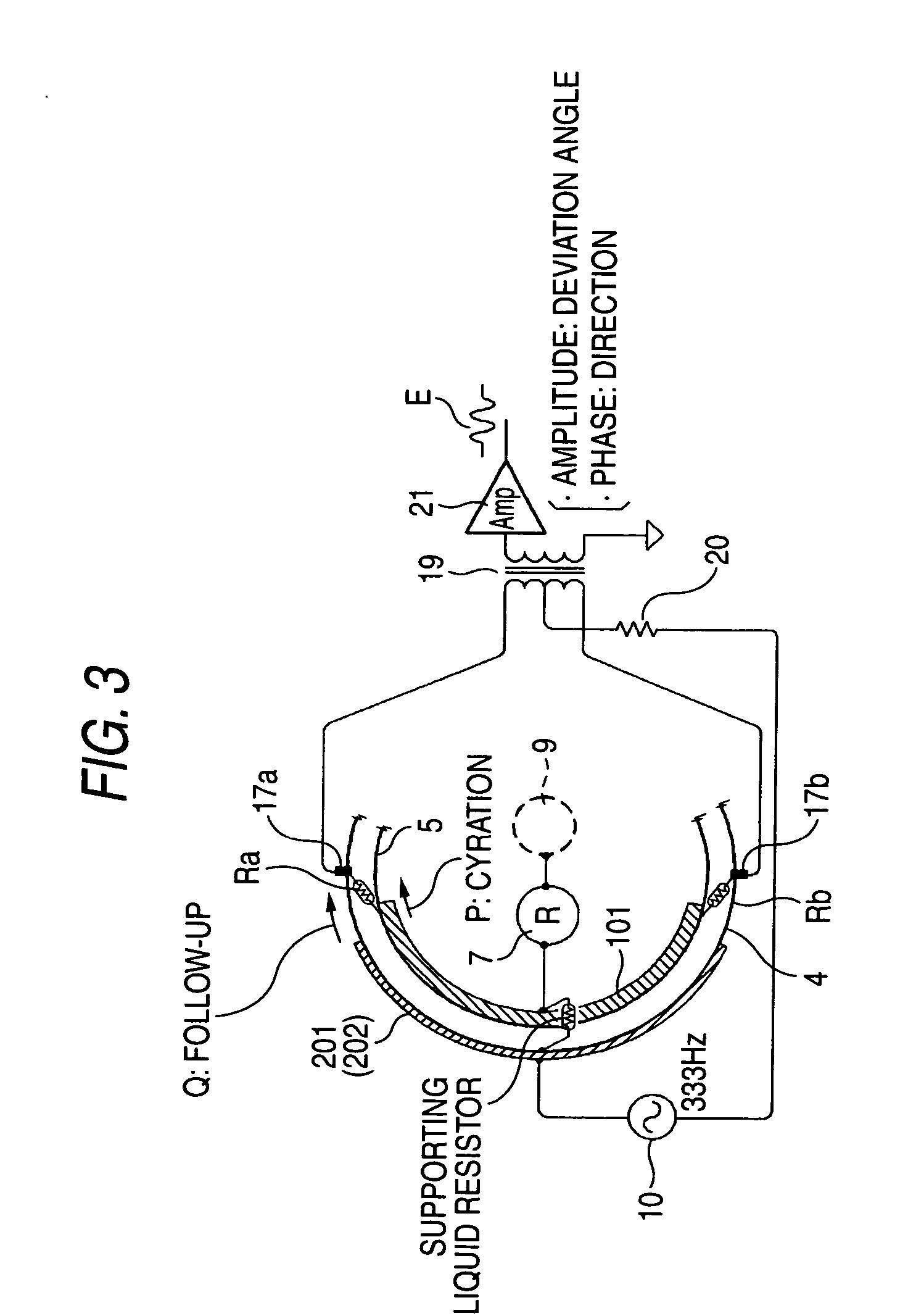
[0027] Further, since the Wheatstone bridge circuit can be mounted in the same way as in the conventional case, a product which ensures follow-up accuracy equivalent to conventional one can be provided without increasing the cost.

Problems solved by technology

(2) If mercury is used in the electrolyte, ions are adsorbed on the center pin surface, the mercury surface, and the pot-like metal portion of the gyrosphere due to the electro-capillarity phenomena, and the intermolecular force of ions acts as a restraining force and hampers the “frictionless free rotation of the gyrosphere,” exerting an adverse effect on the accuracy.

Method used


Image

  • Gyrocompass
  • Gyrocompass
  • Gyrocompass

Examples


Embodiment Construction

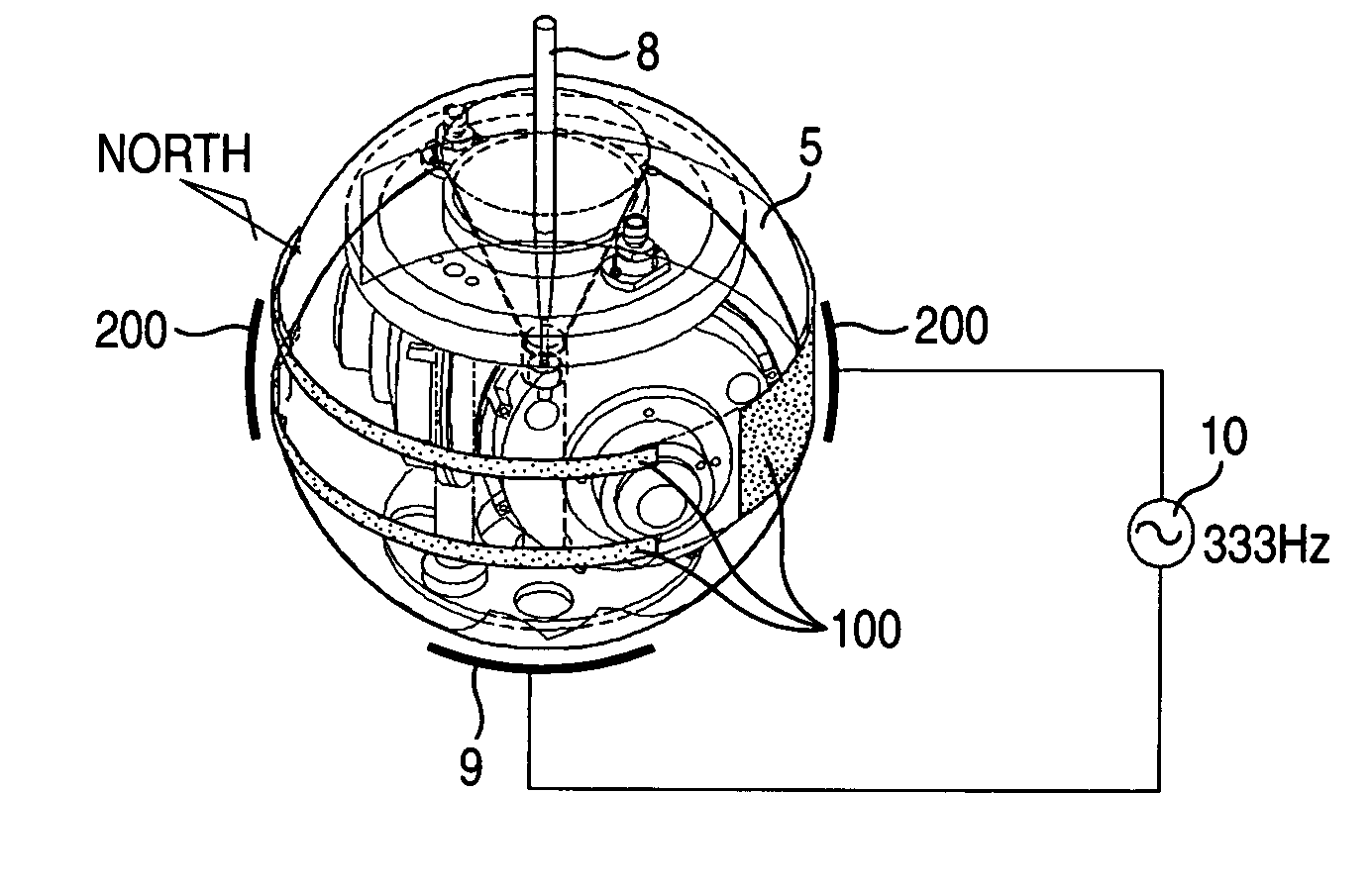
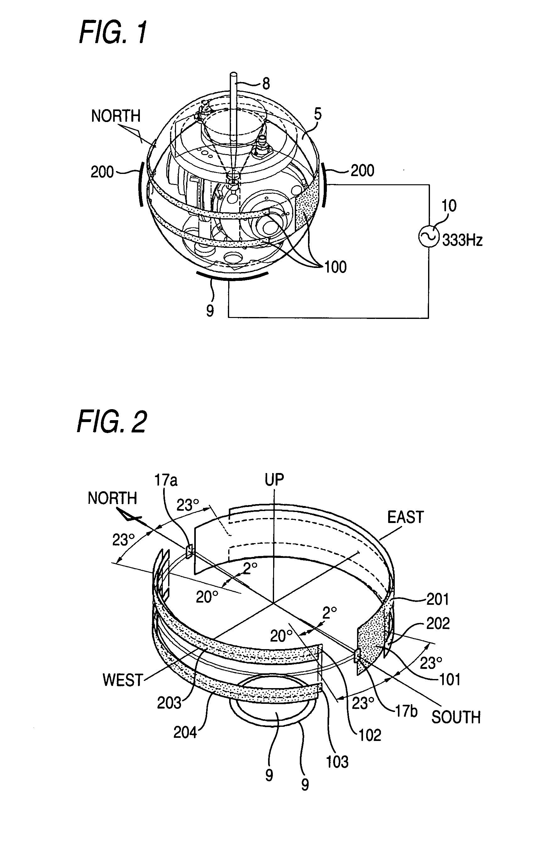
[0036] Embodiments of the invention are described with reference to the drawings. FIG. 1 is a perspective view illustrating an embodiment of a gyrocompass to which the invention is applied, and explains a feeding structure for a gyrosphere 5. Elements identical to those of the conventional gyrocompass described with reference to FIGS. 5 to 8 will be denoted by the same reference numerals, and a description thereof will be omitted. Hereafter, a description will be given of the characteristic portions of the invention.

[0037] In the conventional art (FIGS. 6 and 7), the structure provided is such that a center pin 8 supports a gyrosphere 5, electricity is fed to a gyro rotor by mercury disposed at a tip of this center pin and the dish-shaped electrode in the lower portion, and separate follow-up electrodes are provided.

[0038] In the embodiment, the center pin 8 solely functions to only support the gyrosphere 5. A belt-shaped electrode 200 on the gyrosphere side disposed through the s...


PUM


Abstract

A gyrocompass has a liquid tank containing a supporting liquid therein, a gyrosphere floating in the liquid tank by the supporting liquid and whose central portion is rotatably supported by a center pin provided in an upper portion of the liquid tank, a gyro rotor incorporated in the gyrosphere, two dish-shaped electrodes disposed at a lower portion of the liquid tank and a lower portion of the gyrosphere, and opposed through the supporting liquid, and a pair of follow-up electrodes disposed in a vicinity of a equator of the liquid tank and opposed to be apart by 180°, and two belt-shaped electrodes disposed in vicinities of equators of the liquid tank and the gyrosphere in a state that the follow-up electrodes are located therebetween, and opposed through the supporting liquid, wherein electricity is fed to the gyro rotor through the dish-shaped electrodes and the belt-shaped electrodes.

Description

CROSS-REFERENCE TO RELATED APPLICATIONS [0001] This application is based upon and claims the benefit of priority from the prior Japanese Patent Applications No. 2004-058391, filed on Mar. 3, 2004, the entire contents of which are incorporated herein by reference. BACKGROUND OF THE INVENTION [0002] 1. Field of the Invention [0003] The present invention relates to a feeding structure for a gyro rotor in a gyrocompass which includes a liquid tank containing a supporting liquid therein, a gyrosphere which floats in the liquid tank by means of a supporting liquid and whose central portion is rotatably supported by a center pin provided in an upper portion of the liquid tank, and a gyro rotor incorporated in the gyrosphere. [0004] 2. Description of the Related Art [0005] The following publication is known as a document relating to the gyrocompass having a center pin. [0006]“konpasu to jairo no riron to jissai (Theory and practice of compass and gyro)” published on Oct. 1, 1971 by Kaibundo...

Claims


Application Information

Patent Timeline
IPC IPC(8): G01C19/38G01C19/20
CPCG01C19/38Y10T74/12Y10T74/1271
Inventor TODA, TAKASHI
Owner YOKOGAWA DENSIKIKI
Learn More