Electronic still camera and method of image acquisition of electronic still camera

a still camera and electronic technology, applied in the field of electronic still cameras, can solve the problems of wasteful use of memory space of image storage media, inability to change the size of an area to be cut out (cropping area) for every photographing, and the data size of a photographic image is showing a tendency to increase. , to achieve the effect of avoiding wasteful use of memory spa

Inactive Publication Date: 2005-09-08
NIKON CORP
View PDF7 Cites 35 Cited by
  • Summary
  • Abstract
  • Description
  • Claims
  • Application Information

AI Technical Summary

Benefits of technology

[0009] It is an object of the present invention to provide an electronic still camera and a method of image acquisition of the electronic still camera which can avoid wasteful usage of a memory area of an image storing medium at the time of continuous photographing.

Problems solved by technology

Recently, data size of a photographic image is showing a tendency to increase as the number of pixels of an electronic still camera increases, and it is a significant challenge to usefully use a memory area of an image storage medium for storing the photographic image.
However, applying the cropping function to continuous photographing is not considered according to the conventional electronic still camera, and hence it is impossible to change the size of an area to be cut out (cropping area) for every photographing in the continuous photographing.
As a result of this, when a moving body which moves away from a photographer is subjected to the continuous photographing, for example, the size of the moving body with respect to the image screen becomes smaller over time, and hence the memory area of the image storage medium is wastefully used.
Moreover, according to the cropping methods of the Japanese Unexamined Patent Application Publication No. 2001-236497 and the program “XV”, cropping of a characteristic part in the photographic image is possible, but cropping while paying attention to the moving photographic subject only is impossible.

Method used


Image

  • Electronic still camera and method of image acquisition of electronic still camera
  • Electronic still camera and method of image acquisition of electronic still camera
  • Electronic still camera and method of image acquisition of electronic still camera

Examples


first embodiment

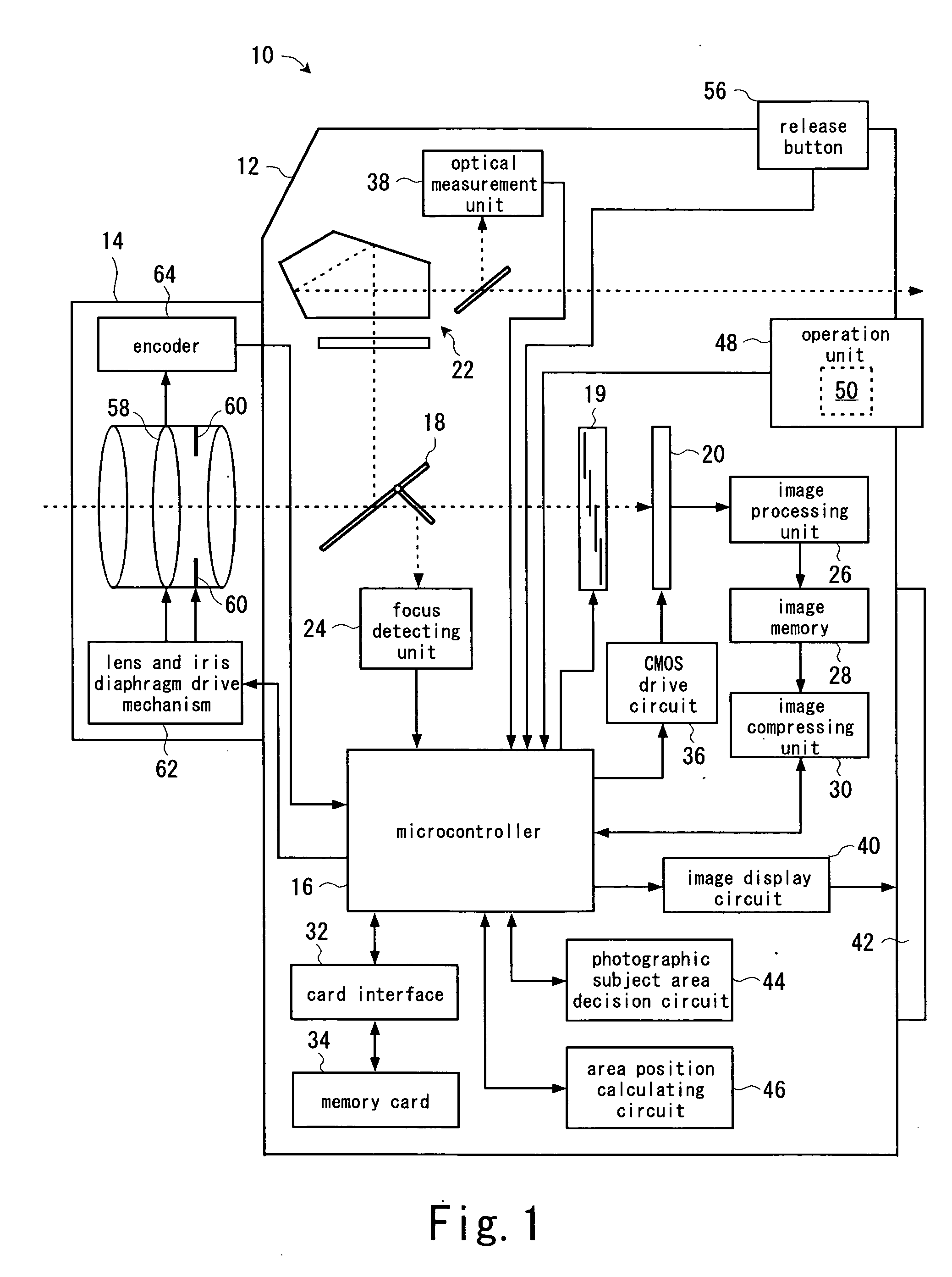
[0032]FIG. 1 shows an electronic still camera of the present invention.

[0033] An electronic still camera 10 is a digital single lens reflex camera, and is constituted of a main unit 12 and a lens unit 14 which is attached to a front surface of a casing of the main unit 12.

[0034] The main unit 12 includes a microcontroller 16 for controlling the electronic still camera 10 as a whole. In the main unit 12, a quick return mirror 18, a mechanical shutter 19, and a light-receiving surface of an imaging device 20 (CMOS sensor) for capturing an image of a subject are disposed on an optical axis of the lens unit 14. In a reflecting direction of the mirror 18 (upper side in the drawing), a finder optical system 22 is disposed. In a reflecting direction of a submirror of the mirror 18 (lower side in the drawing), a focus detecting unit 24 for detecting a focusing state of the subject image is disposed. Focus detecting data which is outputted from the focus detecting unit 24 is supplied to the...

second embodiment

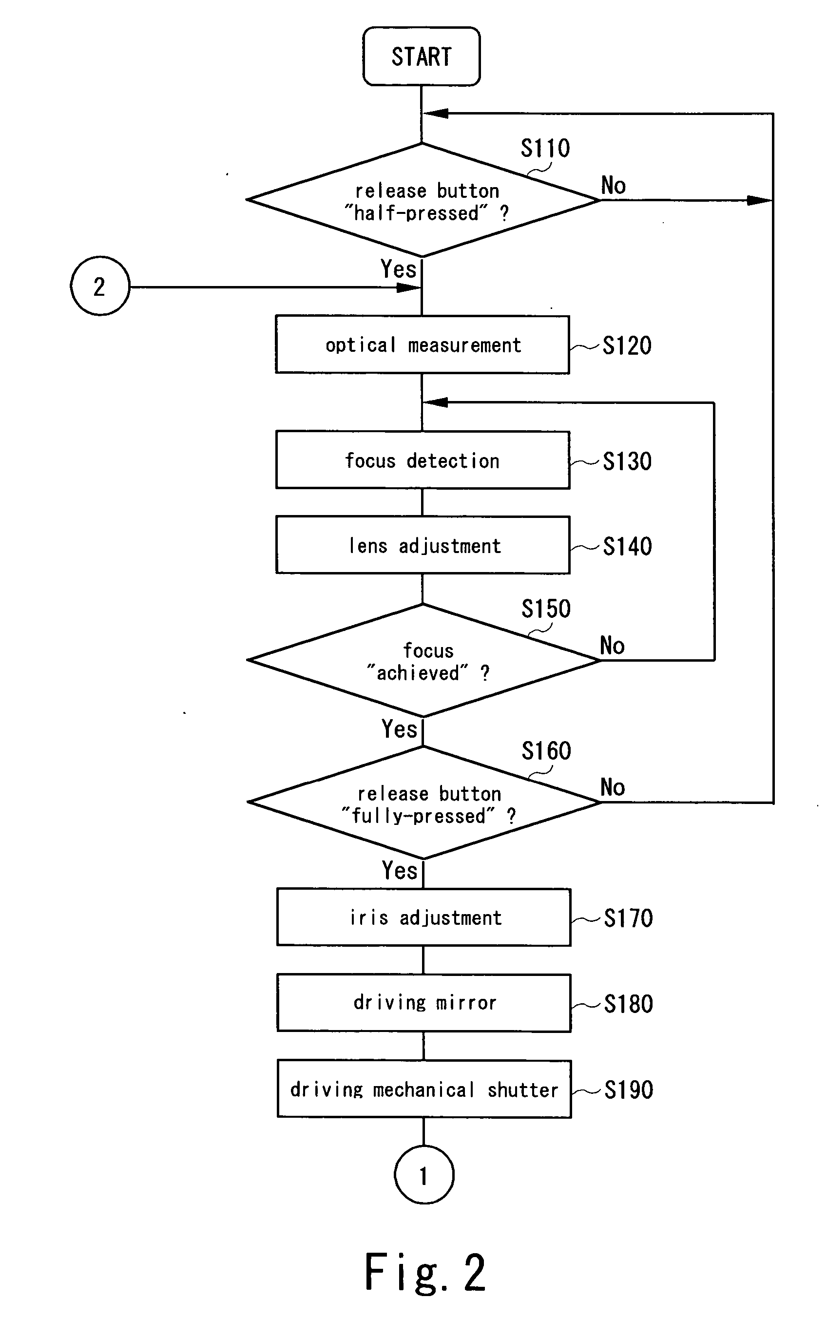
[0075]FIG. 6 and FIG. 7 show photographing operation of the electronic still camera 10a according to the

[0076] Similarly to the first embodiment (FIG. 2), steps S110 to S140 are performed according to operation by a photographer.

[0077] In a step S152, a microcontroller 16 sets a flag FC at “1” when it is determined that focus is achieved in a step S150. Thereafter, processing proceeds to a step S160.

[0078] In a step S154, the microcontroller 16 resets the flag FC to “0” when it is determined that the focus is not achieved in the step S150. Thereafter, processing proceeds to the step S160.

[0079] Then, similarly to the first embodiment (FIG. 2 and FIG. 3), steps S160 to S200 are performed according to operation by the photographer.

[0080] In a step S202, the microcontroller 16 determines whether the flag FC is “1” or not. When the flag FC is “1”, processing proceeds to a step S210. In the step S210, the same processing as that in the step S210 in the first embodiment is performed. ...


PUM


Abstract

A photography mode selecting section allows a photographer to select continuous photographing. An imaging section captures an image of a subject. An area setting section detects a photographic subject based on a photographic image captured by the imaging section for every photographing in the continuous photographing, and sets the size and position of a photographic subject area including the detected photographic subject, when the continuous photographing is selected by the photography mode selecting section. A memory section stores an image inside the photographic subject area as a photographic subject image. Consequently, in continuous photographing of a moving body, the size of the photographic subject area for every photographing in the continuous photographing can be changed according to change in the size of the image of the moving body with respect to an image screen of the imaging section, thereby preventing wasteful usage of a memory area of the memory section.

Description

CROSS-REFERENCE TO RELATED APPLICATIONS [0001] This application is based upon and claims the benefit of priority from Japanese Patent Application No. 2004-060341, filed on Mar. 4, 2004, the entire contents of which are incorporated herein by reference. BACKGROUND OF THE INVENTION [0002] 1. Field of the Invention [0003] The present invention relates to an electronic still camera which has a continuous photographing function for performing successive photographing for a plurality of times in response to a request for photographing. [0004] 2. Description of the Related Art [0005] Recently, data size of a photographic image is showing a tendency to increase as the number of pixels of an electronic still camera increases, and it is a significant challenge to usefully use a memory area of an image storage medium for storing the photographic image. As a technique for saving the memory area of the image storage medium, a cropping function which cuts out a necessary part of the photographic ...

Claims


Application Information

Patent Timeline
Patent Type & Authority Applications(United States)
IPC IPC(8): H04N5/228H04N5/225H04N5/232H04N5/907H04N5/91H04N101/00
CPCH04N5/772H04N5/23296H04N23/69
Inventor IDE, HISATO
Owner NIKON CORP
Why Eureka
Try Eureka