Cartridge, indentification information tag and image forming device
Inactive Publication Date: 2005-09-08
FUJIFILM BUSINESS INNOVATION CORP
View PDF8 Cites 72 Cited by
Summary
Abstract
Description
Claims
Application Information
AI Technical Summary
This helps you quickly interpret patents by identifying the three key elements:
Problems solved by technology
Method used
Benefits of technology
Benefits of technology
[0014] To solve the above-mentioned problems, the present invention intends to provide a cartridge, an identification information tag and an image informing device that can drastically reduce costs of manufacturing and stock as well as facilitate manufacturing and inventory control.
Problems solved by technology
Further, to prevent troubles due to attachment and use of a non-genuine cartridge in the image forming device, the non-genuine cartridge often cannot be attached.
Thus, it is very difficult to use non-genuine products.
Further, provision of the hard key or logo mark that varies with destinations causes a lot of problems in terms of manufacturing management.
Furthermore, it also generates a problem that the cartridge with the hard key or logo mark in a wrong shape may be shipped.
Method used
Image
Click on the blue label to locate the original text in one second.
Reading with bidirectional positioning of images and text.
Examples
first embodiment
1. First Embodiment
[0041] A laser printer that is an example of the image forming device of this invention and a wireless communication system of the laser printer will be described below with reference to figures.
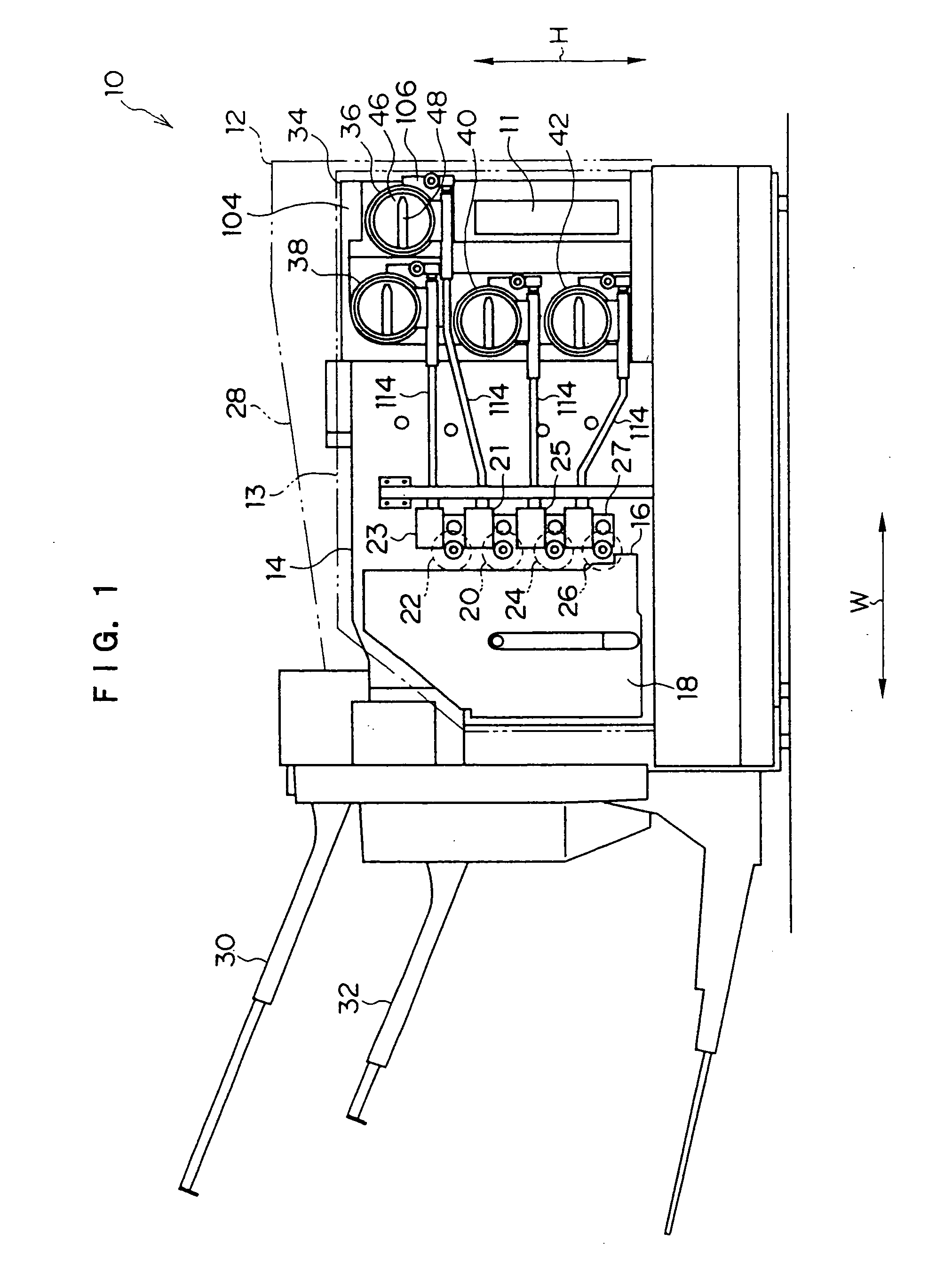
[0042]FIG. 1 shows overall configuration of a laser printer 10 of a first embodiment.
[0043] By a publicly known electrophotograph process, the laser printer 10 forms a toner image in accordance with image information input from an external device, transfers and fixes the formed toner image on recording paper or the like to form an image. Here, electrophotograph process refers to a series of process of recording an image on a recording member by transferring the toner image formed on an electrophotograph photosensitive body through electrification to the electrophotograph photosensitive body, formation of an electrostatic latent image by laser exposure and development of the electrostatic latent image by toner, on the recording member and...
embodiment
(Function of Embodiment)
[0111] Next, function of the laser printer 10 thus configured in accordance with this embodiment will be described.
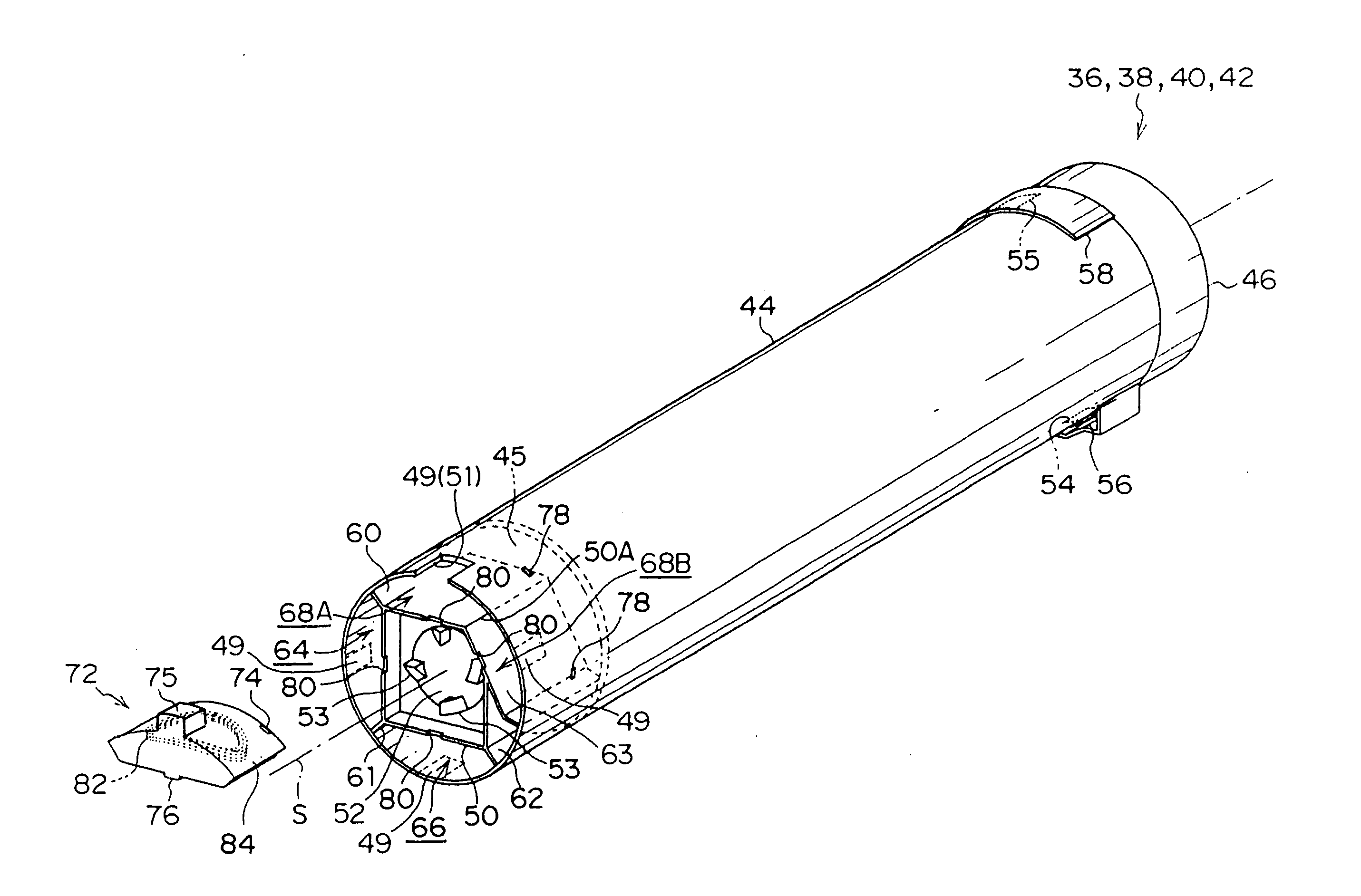
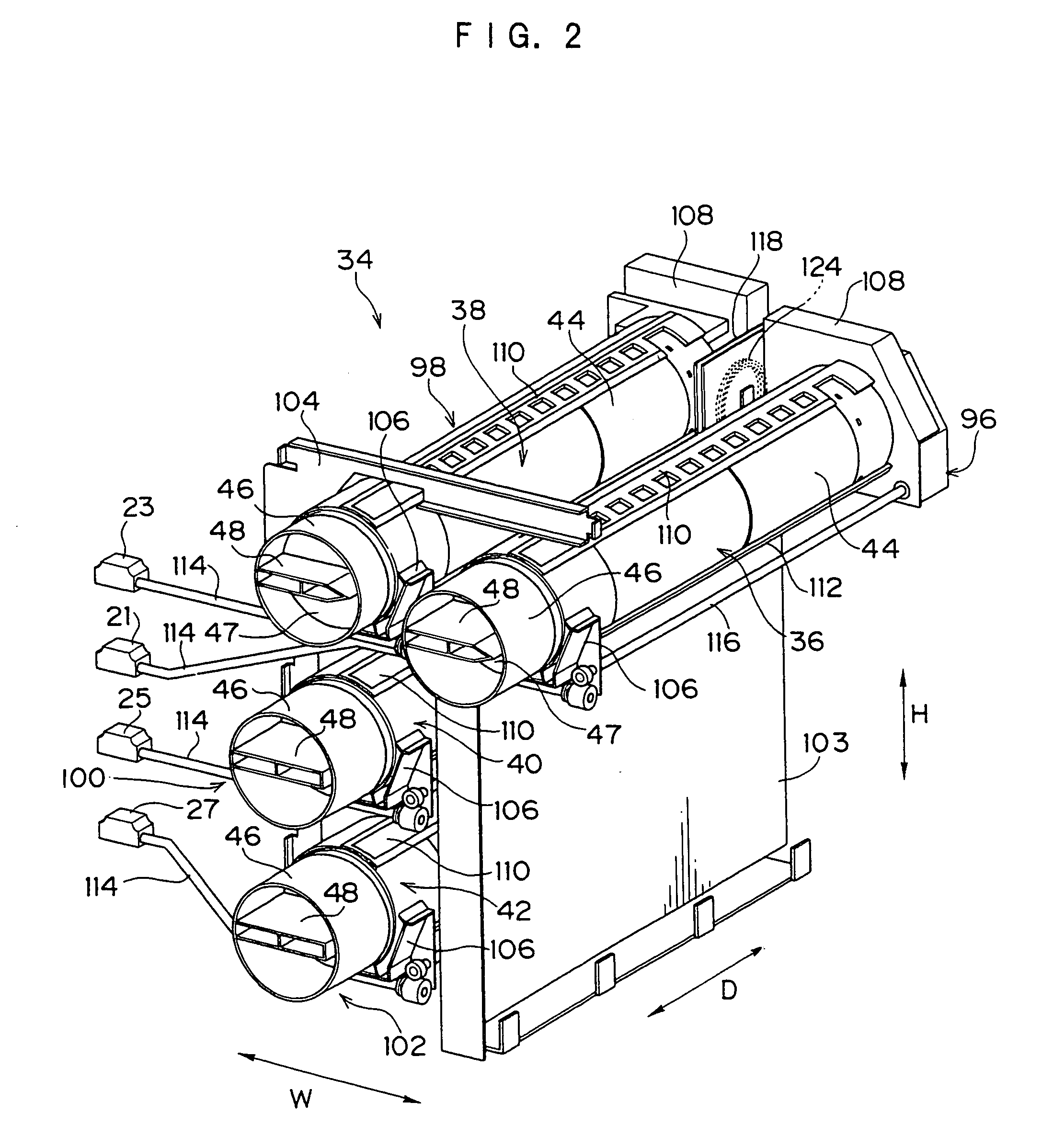
[0112] In the wireless communication system 128 of the laser printer 10 in accordance with this embodiment, since the tag antenna 82 disposed at each of the toner cartridges 36, 38, 40 and 42 is supported by the toner cartridges 36, 38, 40 and 42 so that the coil axis TC is substantially orthogonal to the inserting direction with respect to the detachment portions 96, 98, 100 and 102, respectively, the tag antenna 82 need not to be disposed so as to cover end faces of the toner cartridges 36, 38, 40 and 42. Therefore, even if the cap portion 46 and the driven connecting plate 52 are disposed on the end faces of the toner cartridges 36, 38, 40 and 42, the wireless communication tag 72 can be attached to the toner cartridges 36, 38, 40 and 42 so as not to interference with these components.
[0113] Moreover, in the laser printer 10 in accordance wi...
second embodiment
2. Second Embodiment
[0117] Another embodiment of the toner cartridge used in the laser printer in accordance with the first embodiment will be described below.
[0118] In toner cartridges 36, 38, 40 and 42 in accordance with a second embodiment, as shown in FIG. 16, on the outer peripheral wall of the storage chamber 68A are provided a cutting portion 249A and a cutting portion 249B that are adjacent to each other with being partly overlapped. And, fixing ribs 268A, 268B and 268C for fixing a wireless communication tag 272 are formed on the inside wall 50 along the axis direction of the cartridge body 44.
[0119] On the other hand, as shown in FIG. 17, recessed grooves 274A, 274B and 274C that engage with the fixing ribs 268A, 268B and 268C, respectively, are formed on the bottom face of the wireless communication tag 272 attached to the storage chamber 68A.
[0120] When the wireless communication tag 272 is attached to the storage chamber 68A, as shown in FIG. 16, either the cutting p...
PUM
Abstract
A cartridge of the invention is a cartridge detachably attached to an image forming device, and an identification information tag that stores identification information for distinguishing the cartridge from other cartridge therein is attached, and an identification key that mechanically engages with the image forming device and distinguishes whether or not the cartridge can be attached is provided on the identification information tag. The invention also relates to the identification information tag that is attached to the cartridge detachably attached to the image informing device and stores identification information for distinguishing the cartridge from other cartridge therein. The above-mentioned identification information tag is characterized by providing the identification key that mechanically engages with the image forming device and distinguishes whether or not the cartridge can be attached. The invention also relates to the image forming device to which the cartridge is attached. When the cartridge is attached the cartridge attachment portion, the image forming device mechanically identifies whether or not the cartridge can be attached by using the identification key provided on the identification information tag attached to the cartridge.
Description
CROSS-REFERENCE TO RELATED APPLICATION [0001] This application claims priority under 35 USC 119 from Japanese Patent Application No. 2004-064337, the disclosure of which is incorporated by reference herein. BACKGROUND OF THE INVENTION [0002] 1. Field of the Invention [0003] The present invention relates to a cartridge, an identification information tag and an image forming device. [0004] 2. Description of the Related Art [0005] In an image forming device such as a color printer or copyingmachine, it has become common to use a color toner cartridge that fills toner of yellow (Y), magenta (M), cyan (C) or black (K), respectively, therein for the convenience of supplying toner or to pack a photosensitive drum and peripheral components in a detachable central processing unit so as to serve the convenience of maintenance and repair. [0006] In the image forming device using attached color toner cartridges, since attachment of the cartridge at a wrong position causes color mixture, each c...
Claims
Application Information
Patent Timeline
Application Date:The date an application was filed.
Publication Date:The date a patent or application was officially published.
First Publication Date:The earliest publication date of a patent with the same application number.
Issue Date:Publication date of the patent grant document.
PCT Entry Date:The Entry date of PCT National Phase.
Estimated Expiry Date:The statutory expiry date of a patent right according to the Patent Law, and it is the longest term of protection that the patent right can achieve without the termination of the patent right due to other reasons(Term extension factor has been taken into account ).
Invalid Date:Actual expiry date is based on effective date or publication date of legal transaction data of invalid patent.

