
Image recording apparatus

a technology of image recording and guide plate, which is applied in the direction of power drive mechanism, printing, ink ribbon, etc., can solve the problems of difficult operation of carriage guide plate attachment/detachment relative to carriage guide plate, and achieve the effect of accurate movement and easy detachmen

Active Publication Date: 2005-09-08
BROTHER KOGYO KK
View PDF4 Cites 16 Cited by
  • Summary
  • Abstract
  • Description
  • Claims
  • Application Information

AI Technical Summary

Benefits of technology

[0010] The present invention provides an image recording apparatus in which a guide shaft is not used, an attachment / detachment operation of a carriage is easy, and manufacturing cost can be reduced.
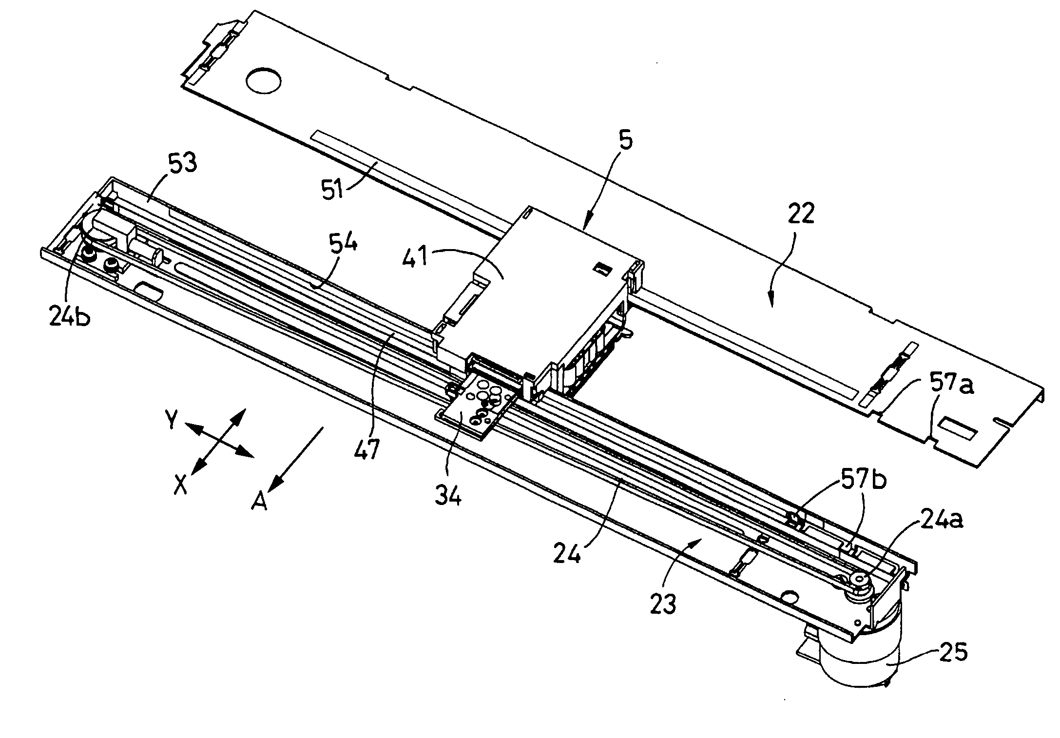
[0012] Since the first sliding convex part protruding from the lower surface side of the carriage comes in contact with the first sliding surfaces of the respective upper surfaces of the horizontal first and second guide member, the carriage can be moved in the main scanning direction in a state where it is supported on both of the guide members by only the weight of the carriage. Since the carriage includes the coming-out preventing pawl to hold the back surface (lower surface side) of at least one of the first and second guide members, the carriage is not detached from the guide members at the time of movement. Only at the time when the coming-out preventing pawl is positioned at the notch part provided at the specified position, the carriage can be easily detached from the guide members. Thus, it is unnecessary to remove the coming-out preventing pawl from the carriage, and there is obtained an effect that the structure becomes very simple, and the cost can be reduced.
[0014] When the carriage is moved along the first and second guide members, the carriage does not float and can be accurately moved with reference to the second sliding surface. Even if the first sliding surface and the second sliding surface orthogonal to each other exist on the second guide member, there is obtained an effect that the carriage can be easily detached from the guide members at the specified position and can be exchanged without removing the coming-out preventing pawl provided on the carriage.

Problems solved by technology

Thus, in order to detach the carriage from the first carriage guide plate, it becomes necessary to perform such an operation as to detach the lower third guide part from the carriage, and there is a problem that the attachment / detachment operation of the carriage relative to the carriage guide plate is difficult.

Method used


Image

  • Image recording apparatus
  • Image recording apparatus
  • Image recording apparatus

Examples


Embodiment Construction

[0035] Now, an embodiment of the invention will be described.

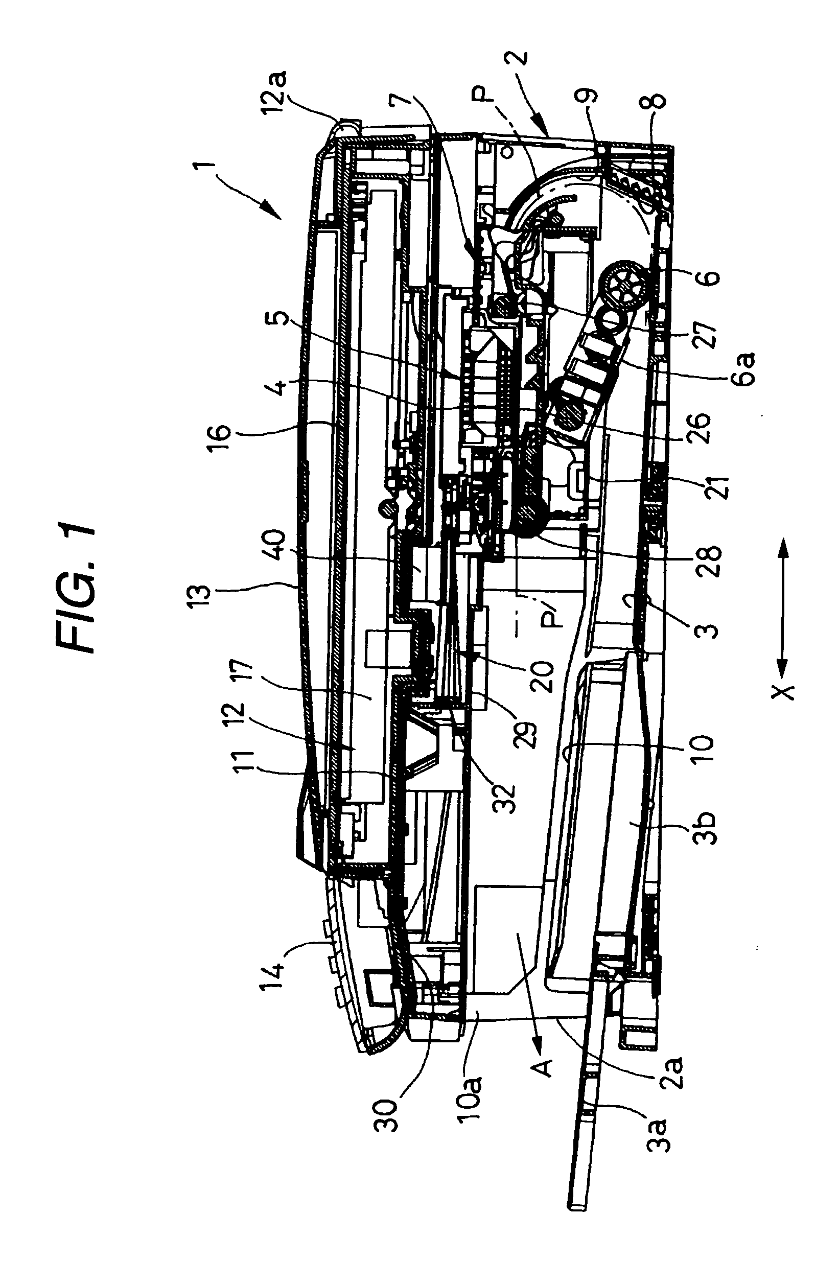
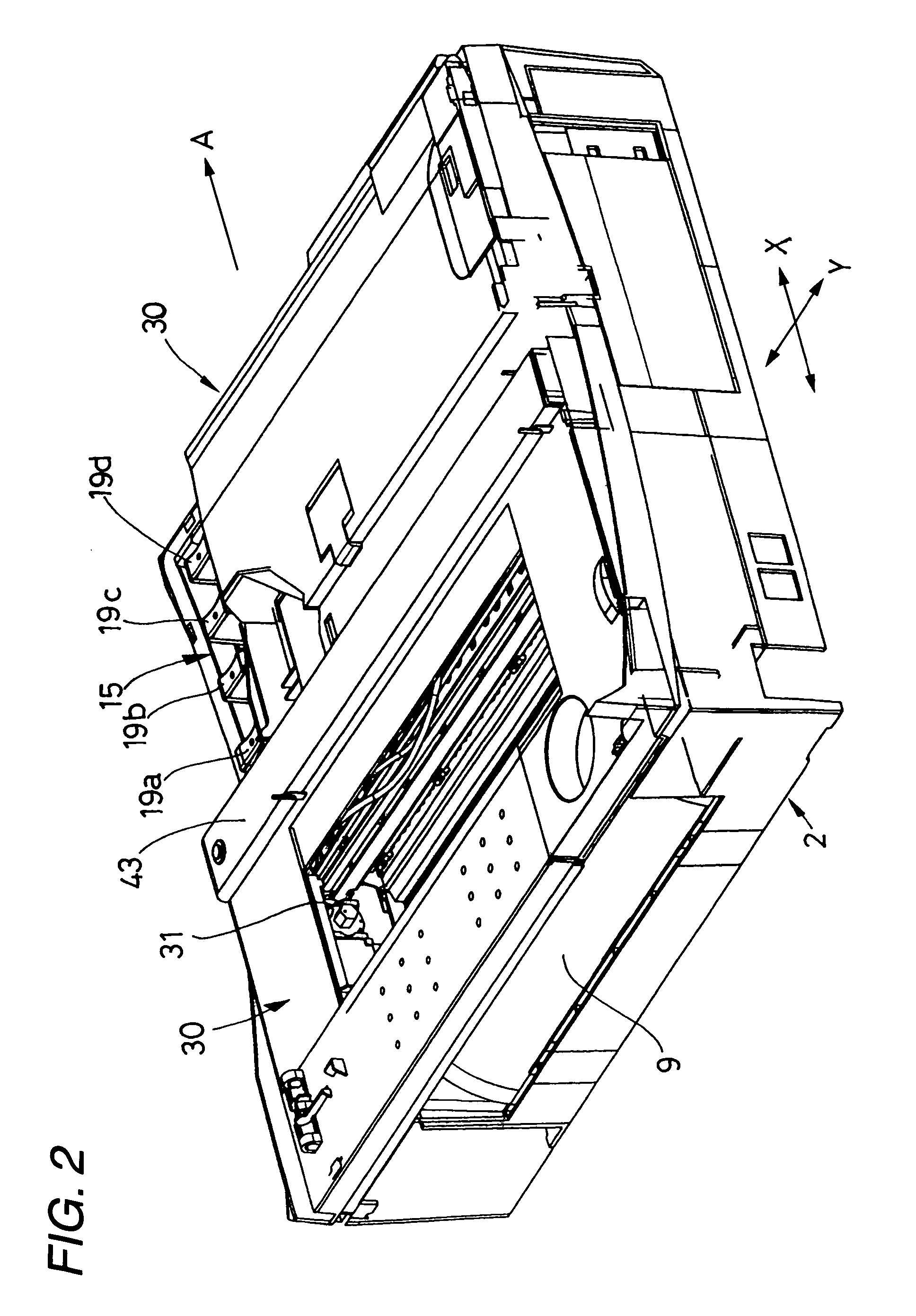
[0036] An image recording apparatus 1 of this embodiment is a multi function device (MFD) having a printer function, a copy function, a scanner function and a facsimile function, to which the invention is applied. As shown in FIG. 1, at a bottom part of a recording apparatus main body 2 made of synthetic resin, a paper feed cassette 3 is disposed which can be inserted through an opening part 2a at the front side (left side in FIG. 1) of the recording apparatus main body 2.

[0037] In this embodiment, the paper feed cassette 3 is made to have such a form that plural sheets P, each of which is a recording medium and is cut into, for example, A4 size, letter size, legal size, postcard size or the like, can be stacked (deposited) and contained in such a manner that its short side extends in a direction (direction orthogonal to the surface of the sheet of FIG. 1, main scanning direction, or Y-axis direction) orthogonal to a she...


PUM


Abstract

An image recording apparatus includes: a first guide member having a first sliding surface; a second guide member having another first sliding surface; and a carriage being supported by the first sliding surfaces of the first and second guide members. The carriage includes first sliding convex parts protruding from a lower surface side thereof and coming in contact with the first sliding surfaces of the first and second guide members, and a coming-out preventing pawl disposed to hold at least one of the first and second guide members in cooperation with the first sliding convex part. At least one of the first and second guide members includes a notch part at a specified position, and the carriage is detachable from the first and second guide members by causing the coming-out preventing pawl to pass through the notch part.

Description

BACKGROUND OF THE INVENTION [0001] 1. Field of the Invention [0002] The present invention relates to an image recording apparatus of an ink-jet type or the like, and more particularly to a structure of a supporting device of a carriage on which a recording head is mounted. [0003] 2. Description of the Related Art [0004] A dominating conventional image recording apparatus is such that for example, as disclosed in JP-A-5-270091 (see FIGS. 1 to 4), in order to support a carriage carrying a recording head in such a manner that it can reciprocate in a main scanning direction, the carriage is slidably supported by a cylindrical guide shaft. [0005] According to the cylindrical guide shaft, because of excellent size accuracy, high rigidity, a variation of a so-called paper gap between the nozzle surface of the recording head and the surface of a recording medium can be made small, and a high quality recording image can be easily obtained, however, the cost is high. Besides, when the carriag...

Claims


Application Information

Patent Timeline
IPC IPC(8): B41J19/00B41J2/175B41J19/20B41J19/42B41J19/66B41J25/304B41J25/34B41J29/02
CPCB41J29/02B41J19/20
Inventor ISHIKAWA, KANKAWAMATA, NORIYUKI
Owner BROTHER KOGYO KK
Learn More