Cylindrical catalytic heater

a catalytic heater and cylindrical technology, applied in the field of catalytic heaters, can solve the problem of not being able to provide heat for a number of people centrally, and achieve the effect of improving heat dissipation efficiency and reducing heat dissipation

Inactive Publication Date: 2005-09-08
THE COLEMAN CO INC
View PDF21 Cites 10 Cited by
  • Summary
  • Abstract
  • Description
  • Claims
  • Application Information

AI Technical Summary

Benefits of technology

[0008] The cylindrical catalytic heater is capable of providing heat in all directions simultaneously; i.e., in a 360 degree pattern. In addition, the movable reflector permits the heat to be directed in a desired direction, providing much flexibility for the cylindrical catalytic heater.

Problems solved by technology

While the prior art catalytic heaters work well for their intended purpose, because they are directed in a single direction, they cannot be positioned centrally to provide heat for a number of people.

Method used


Image

  • Cylindrical catalytic heater
  • Cylindrical catalytic heater
  • Cylindrical catalytic heater

Examples


Embodiment Construction

[0014] In the following description, various embodiments of the present invention will be described. For purposes of explanation, specific configurations and details are set forth in order to provide a thorough understanding of the embodiments. However, it will also be apparent to one skilled in the art that the present invention may be practiced without the specific details. Furthermore, well-known features may be omitted or simplified in order not to obscure the embodiment being described.

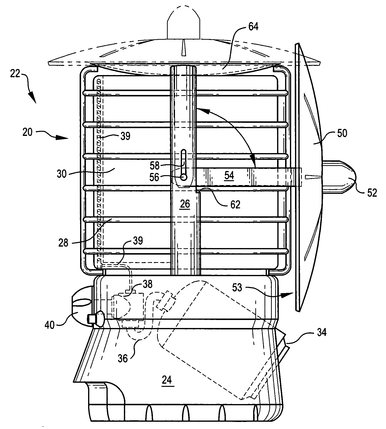
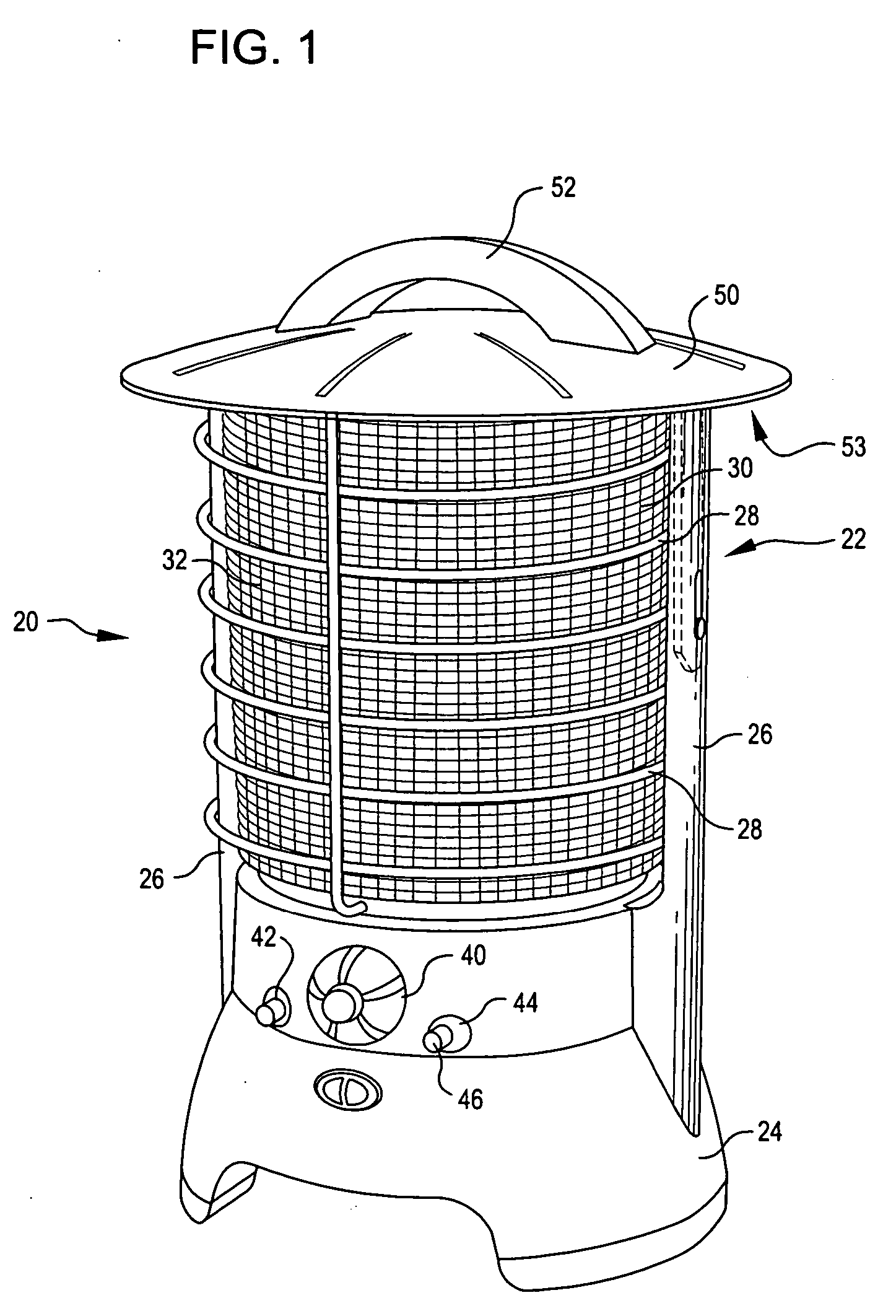
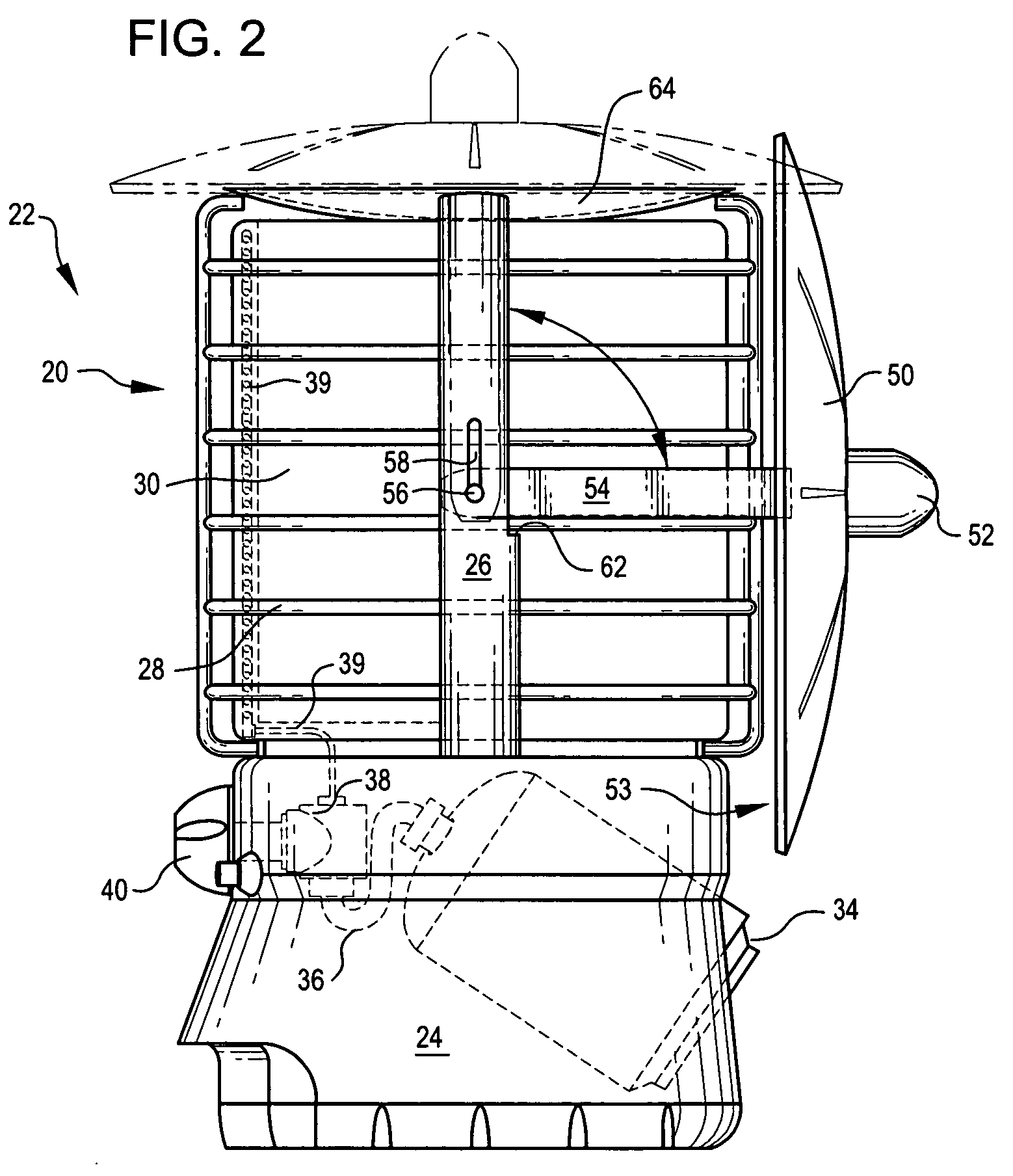
[0015] Referring now to the drawings, in which like reference numerals represent like parts throughout the several views, FIG. 1 shows a cylindrical catalytic heater 20 in accordance with an embodiment. The cylindrical catalytic heater 20 includes a housing 22 having a base 24. Two side rails 26 extend upward from the base 24. A protective grid 28 is attached to the side rails 26 and extends around a combustion chamber 30 for the cylindrical catalytic heater 20.

[0016] The components of a cataly...


PUM


Abstract

A catalytic heater with a cylindrical combustion chamber. The catalytic heater may be positioned centrally to provide heat for a number of people or an area. A reflective top is movable to along a side of the cylindrical combustion chamber for directing the heat in a desired direction. The cylindrical catalytic heater is capable of providing heat in all directions simultaneously; i.e., in a 360 degree pattern. The movable reflector permits the heat to be directed in a desired direction, providing much flexibility for the cylindrical catalytic heater.

Description

TECHNICAL FIELD OF THE INVENTION [0001] The present invention relates generally to heating devices, and more particularly to catalytic heaters. BACKGROUND OF THE INVENTION [0002] A typical catalytic combustion apparatus oxidizes a gaseous fuel, such as methane, butane, or propane, at room temperature to generate heat. Generally, the fuel is introduced into a gas-tight housing where the fuel expands to completely fill the housing. As the fuel diffuses through a catalyst-containing support located at an outlet of the housing, ambient air mixes with the diffused fuel. The fuel-air mixture is then oxidized by a reaction promoted by the catalyst to produce heat. Such catalysts typically include noble metals such as platinum group metals or compounds containing the same. The substrates upon which the catalysts are supported are typically made from glass fibers, porous metals, or ceramics such as ceramic wool or ceramic board and the like. [0003] The products of the catalyst-enhanced oxida...

Claims


Application Information

Patent Timeline
Patent Type & Authority Applications(United States)
IPC IPC(8): F23D14/28F24C3/04
CPCF23D14/18F23D14/28F24C15/22F23D2900/14121F23D2203/1012F24C3/062F23D14/151
Inventor MILLS, DONOVAN DALERADFORD, JUSTIN VANDREW
Owner THE COLEMAN CO INC
Why Eureka
Try Eureka