
Method for monitoring an RF power amplifier, and an RF device, a monitoring device, and an MR system corresponding thereto

a technology of rf power amplifier and monitoring device, which is applied in the direction of transmission monitoring, magnetic variable regulation, instruments, etc., can solve the problem of limited operation of radio frequency power amplifier

Active Publication Date: 2005-09-08
SIEMENS HEALTHCARE GMBH
View PDF7 Cites 31 Cited by
  • Summary
  • Abstract
  • Description
  • Claims
  • Application Information

AI Technical Summary

Benefits of technology

[0011] It is an object of the present invention to provide a method and associated components and systems monitoring a radio frequency power amplifier that safely prevent an excess of radiated radio frequency power above a temporally varying threshold, while enabling a continual measurement without repeated shutdowns (deactivations) of the power amplifier.
[0015] Limitation of the operation of the radio frequency power amplifier can ensue in the inventive method, for example by shutting off the radio frequency power amplifier, temporarily deactivating the radio frequency power amplifier, or reducing the transmission power of the radio frequency power amplifier.
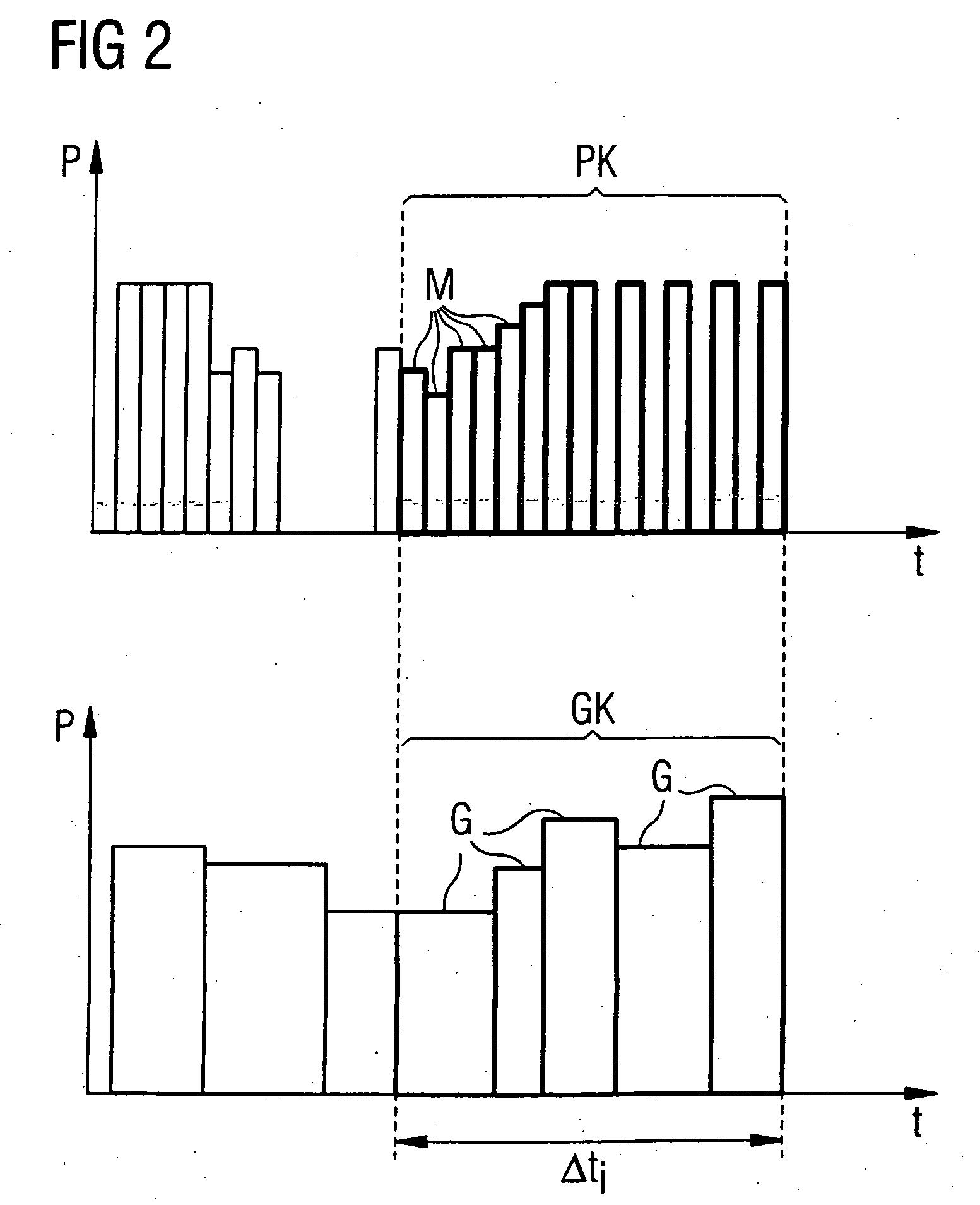
[0019] In principle, it is possible to determine a power limit value effective at this point in time given the measurement of each individual measurement value. For this purpose, for example, both the measurement values and the power limit values can be determined in the same time period. This procedure has the advantage that the control value can be simply formed from the sum of the individual measurement values and the limit control value and the sum of the corresponding power limit values in the respective time window to be monitored. This means that the sums of the measurement values and the power limit values can be directly compared.

Problems solved by technology

Finally, the radio frequency power amplifier is limited in operation if and when the control value reaches or exceeds the limit control value.

Method used


Image

  • Method for monitoring an RF power amplifier, and an RF device, a monitoring device, and an MR system corresponding thereto
  • Method for monitoring an RF power amplifier, and an RF device, a monitoring device, and an MR system corresponding thereto
  • Method for monitoring an RF power amplifier, and an RF device, a monitoring device, and an MR system corresponding thereto

Examples


Embodiment Construction

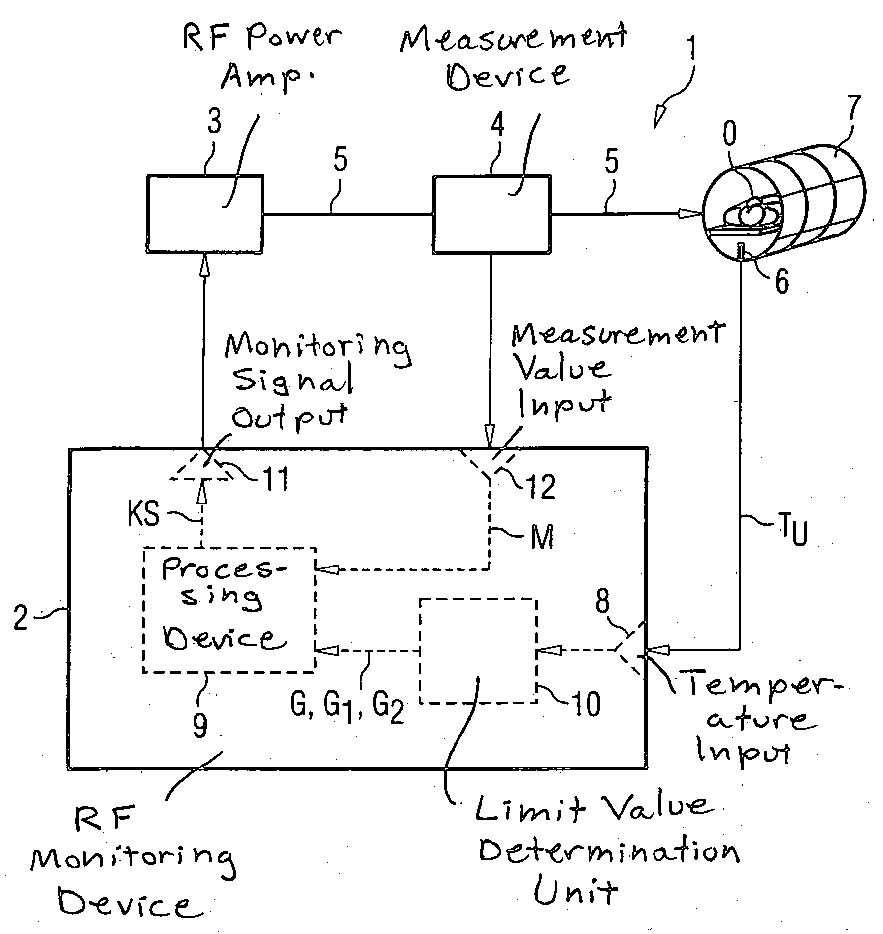
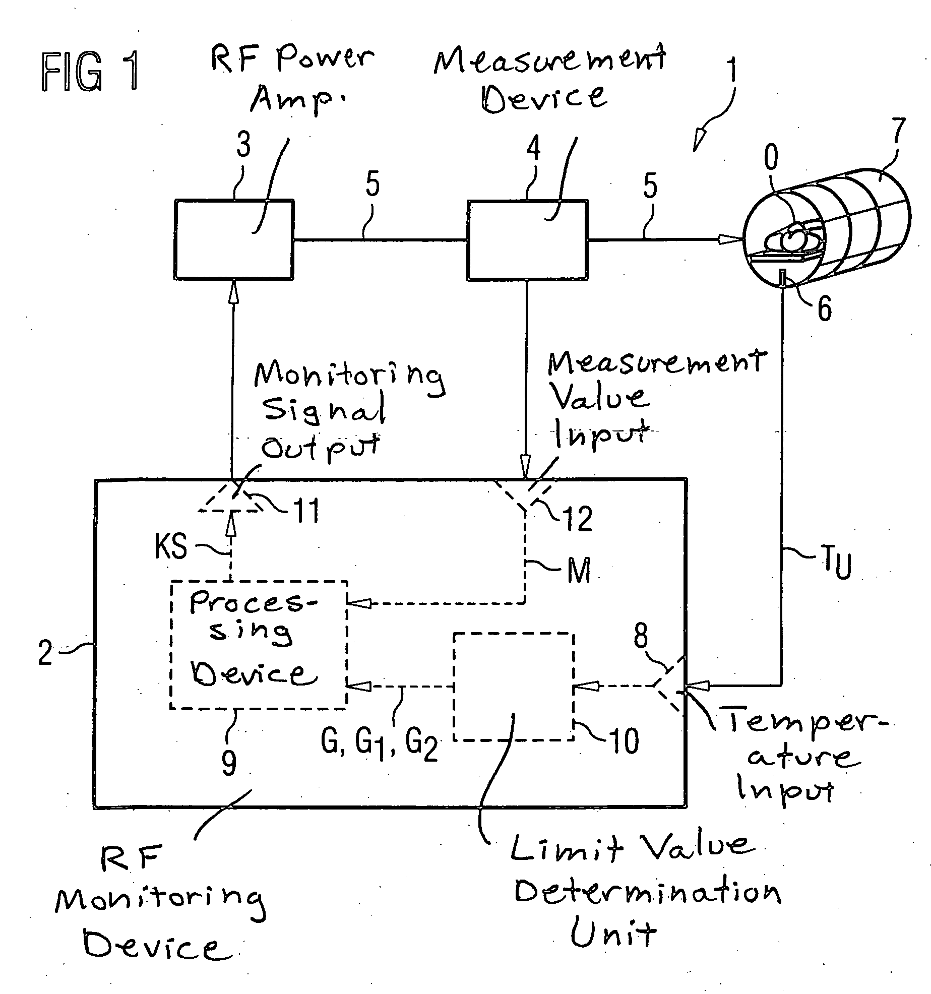
[0035] As a basic component of a magnetic resonance tomography system, FIG. 1 shows a radio frequency device 1. The representation shown in FIG. 1 concentrates on the transmission branch of the radio frequency device 1.

[0036] In addition to the transmission branch of the radio frequency device 1, the magnetic resonance tomography system has a magnet system (not shown) for generation of a basic magnetic field in which at least a part of a patient is disposed during an examination, as well as gradient coils (not shown) to apply magnetic gradient fields. Moreover, a radio frequency reception system (not shown) is provided, with a reception coil and a suitable reception amplifier. The transmission coil can also form the reception coil. An image computer (not shown) reconstructs images from the received signals for display, for example on a screen, and / or for storage in a memory. A control computer (not shown) serves for coordination of the interaction of the individual components.

[003...


PUM


Abstract

In a method for monitoring of a radio frequency power amplifier and a radio frequency device, a radio frequency monitoring device and magnetic resonance tomography system operable according to the method, radio frequency pulses emitted by a radio frequency power amplifier and are transmitted into a human subject by a transmission coil at temporal intervals. Measurement values that represent the power of the radio frequency pulses are measured at temporal intervals, and varying, predetermined power limit values are determined at temporal intervals. A control value representing the radio frequency dose emitted in a time window is determined based on a number of measurement values measured in the time window. Likewise, a limit control value representing a dose limit value allowed in the appertaining time window is determined based on the power limit values determined in the appertaining time window. The radio frequency power amplifier is limited in operation if and when the control value reaches or exceeds the limit control value.

Description

BACKGROUND OF THE INVENTION [0001] 1. Field of the Invention [0002] The present invention concerns a method for monitoring a radio frequency power amplifier, as well as a corresponding radio-frequency device, a corresponding radio-frequency monitoring device and a corresponding magnetic resonance tomography system. [0003] 2. Description of the Prior Art [0004] Magnetic resonance tomography is an imaging modality now in widespread use, which is based on the detection of signals arising from precessing nuclear spins of protons in a body region of an examination subject. First, a strong, stable homogenous magnetic field is generated in which the body region is disposed, which causes a stable alignment of the protons in the body region. This stable alignment is altered by radiating electromagnetic radio frequency energy into the region. After this excitation the magnetic resonance signals created in the body are detected with suitable receiver coils. The signals are processed are proces...

Claims


Application Information

Patent Timeline
Patent Type & Authority Applications(United States)
IPC IPC(8): G01R33/28G01R33/36H03G3/30
CPCG01R33/288G01R33/3614H03G3/3047H03G3/3042G01R33/543
Inventor BIELMEIER, WOLFGANGLUDWIG, KLAUS
Owner SIEMENS HEALTHCARE GMBH
Learn More