
Corner key for exterior jamb and sill

Inactive Publication Date: 2005-09-15
MASONITE CORP
View PDF16 Cites 26 Cited by
  • Summary
  • Abstract
  • Description
  • Claims
  • Application Information

AI Technical Summary

Benefits of technology

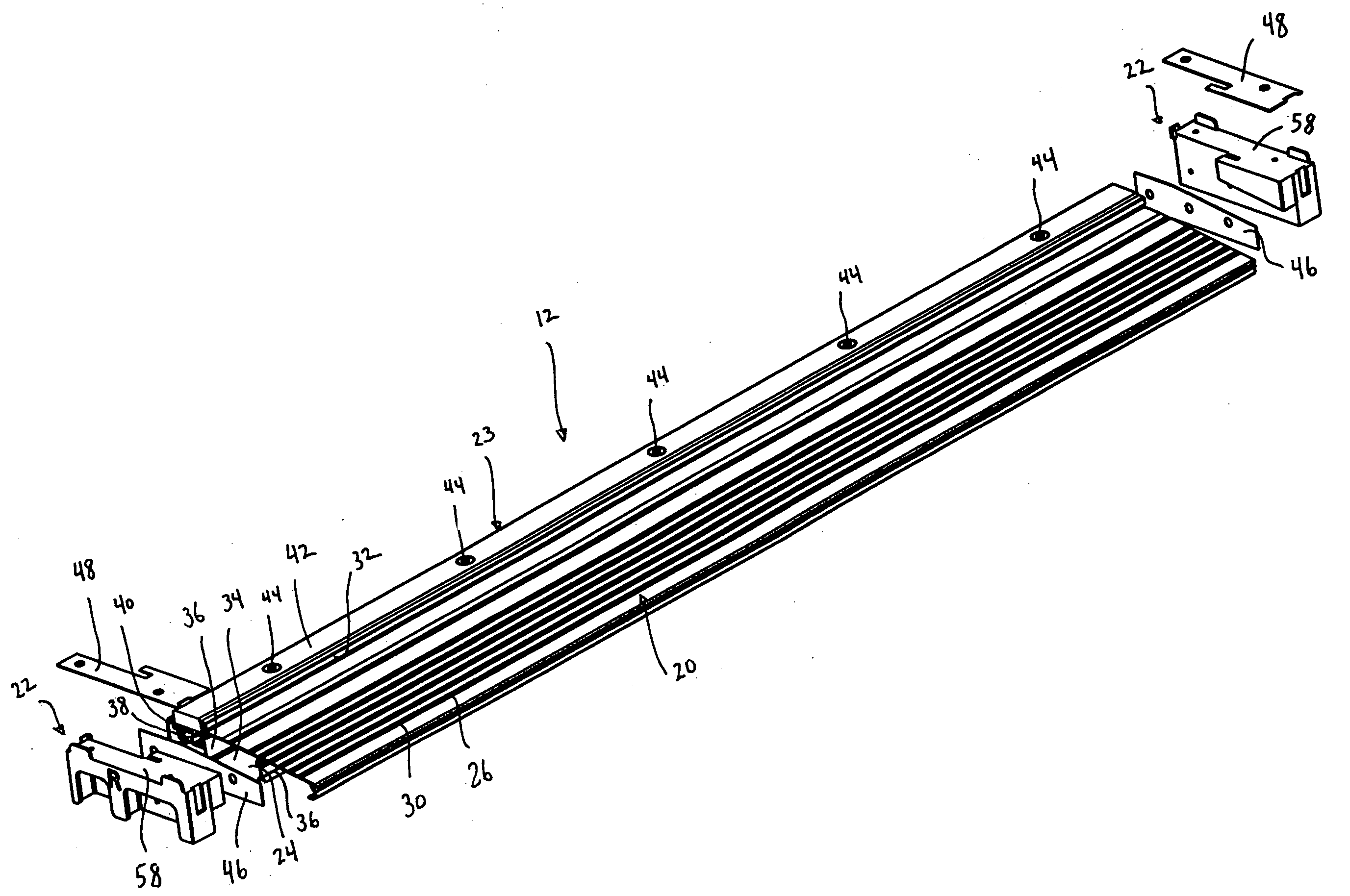
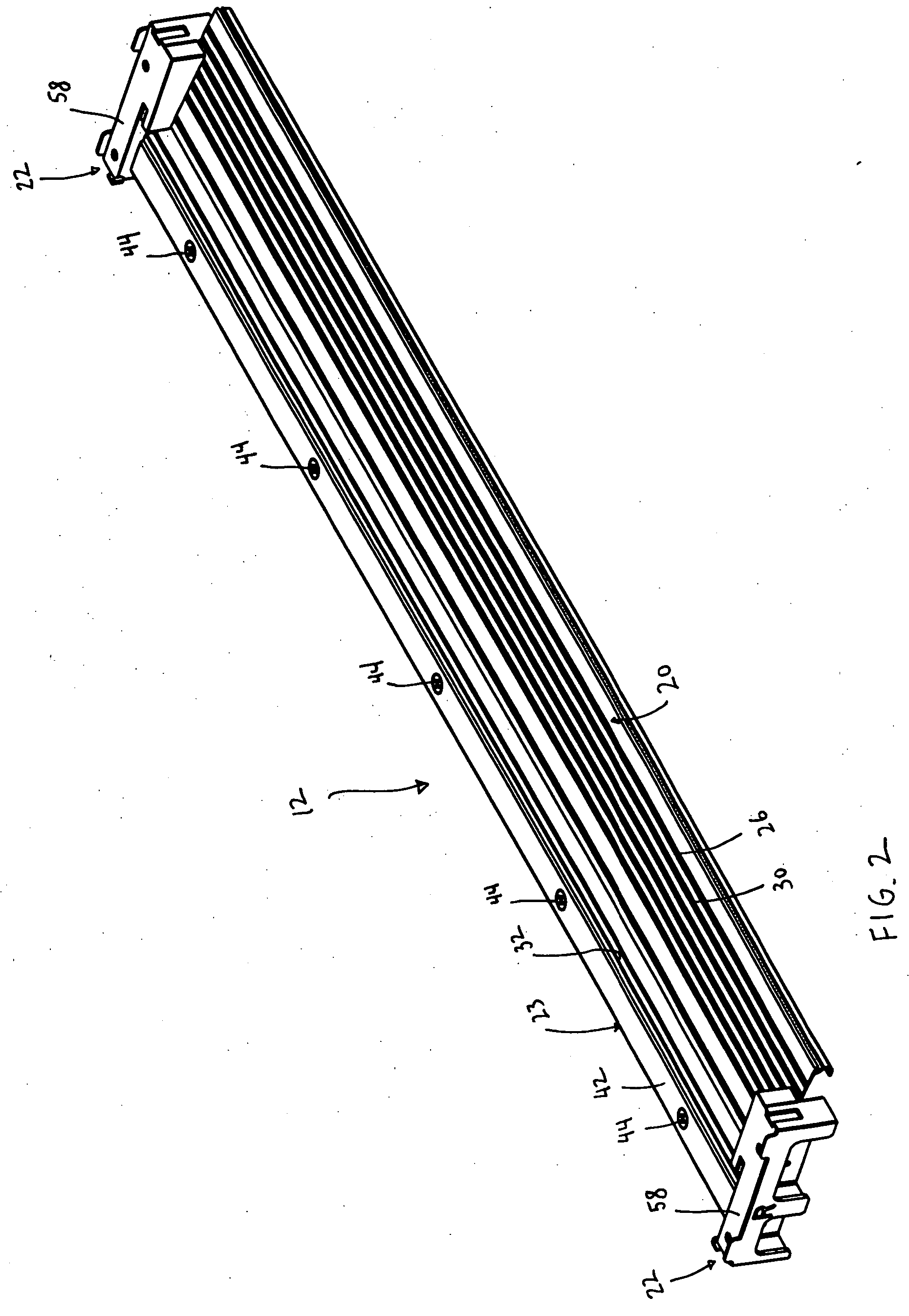
[0008] One aspect of the invention relates to a sill assembly that includes injection molded jamb supports that can be secured to the sill assembly. This aspect of the invention provides a sill assembly for a doorjamb assembly. The doorjamb assembly includes a pair of vertically extending jamb members, a header structure, and at least one door. The sill assembly includes a sill assembly including a sill base and a threshold connected to the sill base. The threshold provides an inclined top surface. A pair of molded jamb supports can be formed in an injection molding process. One of the jamb supports is attached to one end of the sill assembly and the other of the jamb supports is attached to an opposite end of the sill assembly. The jamb supports protrude outwardly from the sill assembly and provide substantially flat jamb support surfaces that engage and support a respective one of the jamb members. The jamb supports are configured such that the jamb supports can be used in connection with both inwardly and outwardly swing doors. The jamb support surfaces are positioned above the top surface of the threshold such that the jamb supports raise the jamb members above the top surface of the inclined threshold whereby the jamb members are not in contact with any water that is standing or draining off the top surface, which can reduce rot. Furthermore, the jamb supports permit the jamb assembly to be easily configured for any size door opening without the need for complex cutting of the jamb.

Problems solved by technology

This type of integral connection has been shown to be undesirable because of the expansion and contraction of these dissimilar components when exposed to moisture, heat and other elements.
Furthermore, this arrangement requires complex cuts be made in the end of the frame to permit mounting to a sill assembly.

Method used


Image

  • Corner key for exterior jamb and sill
  • Corner key for exterior jamb and sill
  • Corner key for exterior jamb and sill

Examples


Embodiment Construction

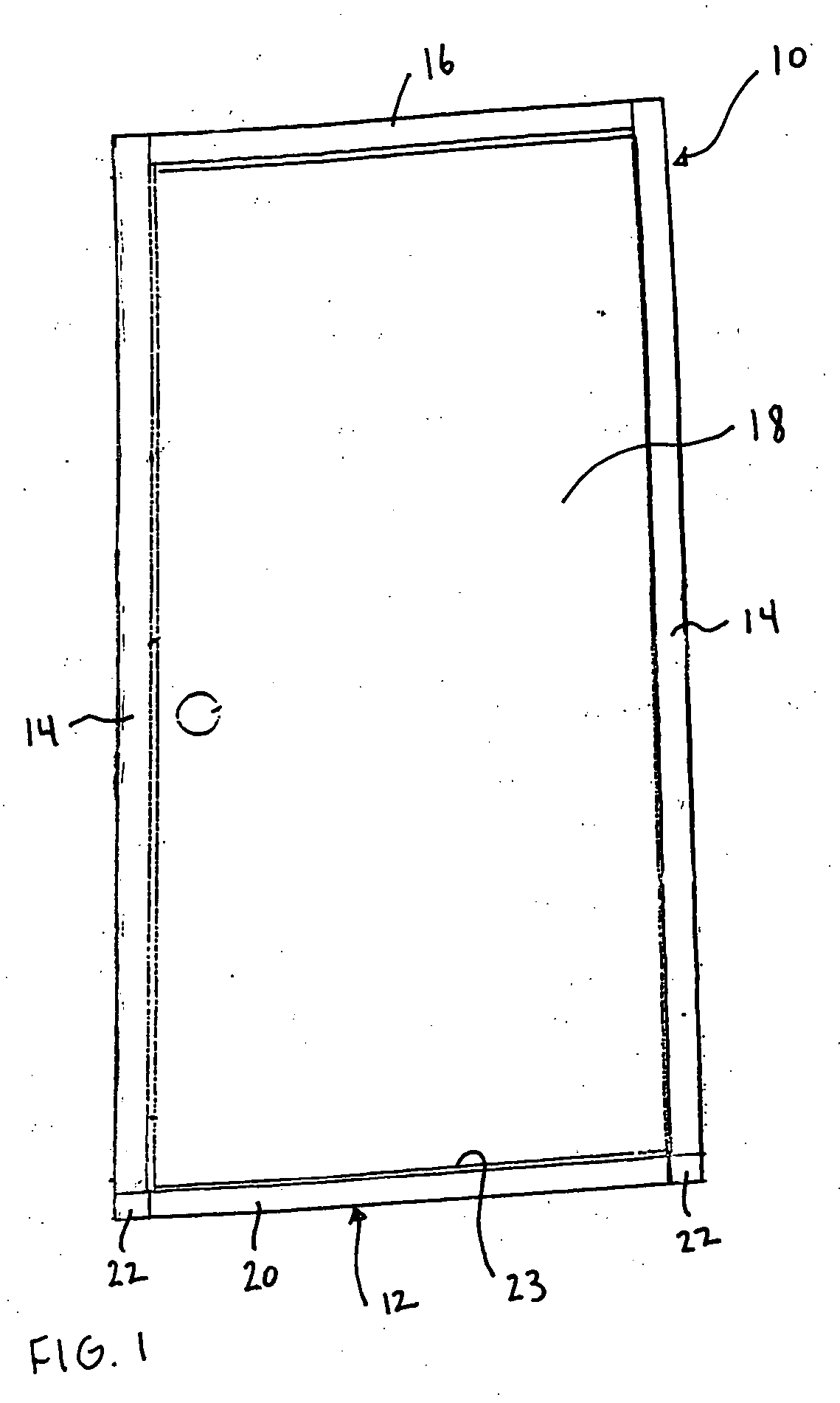
[0059]FIG. 1 illustrates a doorjamb assembly 10 incorporating a sill assembly 12 constructed according to an embodiment of the present invention. The doorjamb assembly 10 includes a pair of vertically extending horizontally spaced jamb members 14, which are typically formed from wood, a horizontally extending header structure 16, which is also typically formed from wood, and at least one door 18. The sill assembly 12 includes an elongated sill assembly 20 with jamb supports 22 attached at opposing ends thereof that are connected to lower ends of the pair of vertically extending jamb members 14. The pair of jamb members 14, the header structure 16, and the threshold and door sill assembly 12 form a generally rectangular door jamb opening within which the at least one door 18 is disposed.

[0060] The sill assembly 12 is not limited to use with the specific configuration of door jamb assembly shown and other various configurations are contemplated, for example, a door jamb assembly may ...


PUM


Abstract

A sill assembly for a doorjamb assembly includes a sill assembly including a sill base and a threshold. The threshold provides an inclined top surface. A pair of jamb supports are formed in an injection molding process with one of the jamb supports being attached to one end of the sill assembly and the other of the jamb supports being attached to an opposite end of the sill assembly. The jamb supports protrude outwardly from the sill assembly and provide substantially flat jamb support surfaces that engage and support a respective one of the jamb members of a doorjamb assembly. The jamb support surfaces are positioned above the top surface of the threshold such that the jamb supports raise the jamb members above the top surface of the inclined threshold.

Description

CROSS REFERENCE TO RELATED APPLICATION [0001] This application claims priority to U.S. Provisional Application No. 60 / 551,365, filed on Mar. 10, 2004, the entire contents of which is incorporated by reference.BACKGROUND OF THE INVENTION [0002] 1. Field of the Invention [0003] The present invention relates to sill assemblies for use in door jam assemblies. In particular, the present invention relates to molded jamb supports for a sill assembly. [0004] 2. Description of Related Art [0005] Known threshold and door sill assemblies are typically placed against the floor and mounted between the lower ends of vertically extending jamb members of a doorjamb assembly. This arrangement allows the lower ends of the jamb members to contact the floor, thereby exposing the end grain of the jamb members to moisture that can lead to rot. [0006] Others have attempted to reduce exposure to moisture by forming the lower portion of the doorjamb from a moisture, decay and insect resistant material. U.S....

Claims


Application Information

Patent Timeline
IPC IPC(8): E06B1/04E06B1/70
CPCE06B1/70E06B3/9632
Inventor BACZUK, ERICWHITE, MATTMASSEY, VICTOR
Owner MASONITE CORP
Learn More