

Radiographic apparatus and control method therefor
a technology control method, which is applied in the direction of radioation control device, television system, instruments, etc., can solve the problems of large voltage fluctuations in gnd and power supply line of x-ray imaging apparatus, no current flow, and large current flow, etc., to shorten the refresh time and the wait time after refresh, and increase the frame frequency
- Summary
- Abstract
- Description
- Claims
- Application Information
AI Technical Summary
Benefits of technology
Problems solved by technology
Method used
Image

Examples
first embodiment
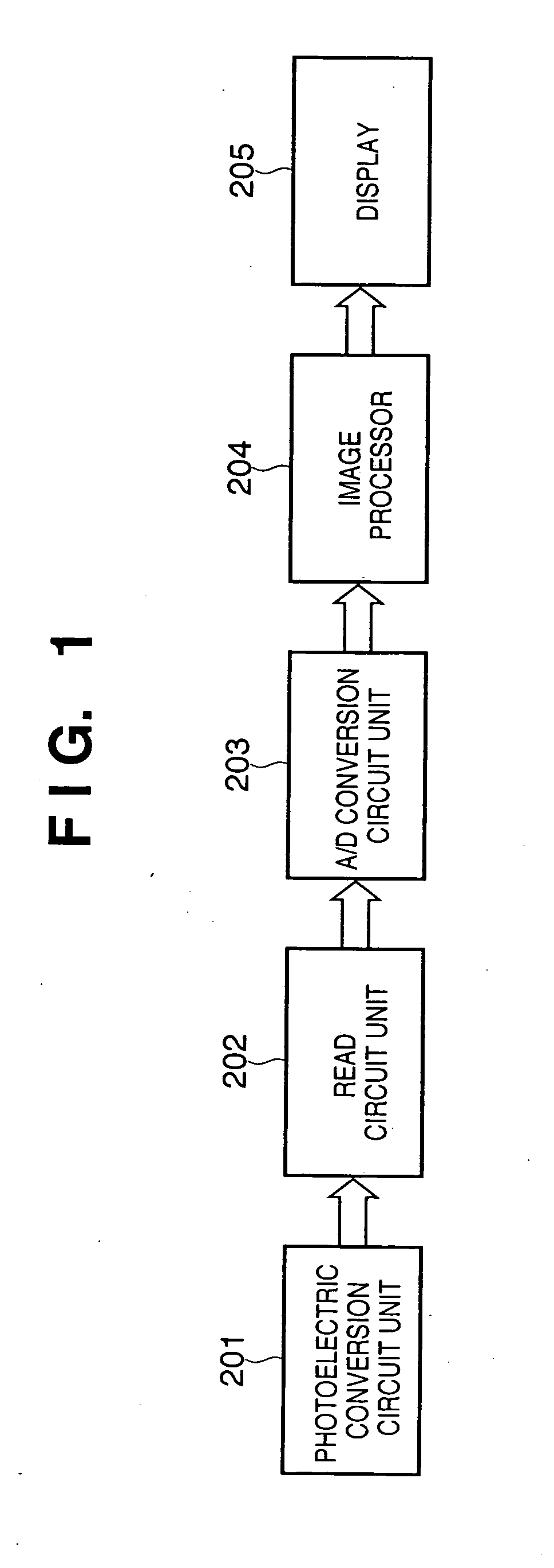
[0042] The first embodiment of the present invention will be explained. FIG. 1 is a block diagram showing the arrangement of an X-ray imaging apparatus (radiographic apparatus) and the flow of image data according to the first embodiment of the present invention.
[0043] The first embodiment comprises a photoelectric conversion circuit unit 201, read circuit unit 202, A / D conversion circuit unit 203, image processor 204, and display 205. Image data output from the photoelectric conversion circuit unit 201 is amplified by the read circuit unit 202, and A / D-converted by the A / D conversion circuit unit 203. The data undergoes image processes such as offset correction and gamma correction by the image processor 204, and is output to the display 205. The resultant data is used for diagnosis by the radiographer.
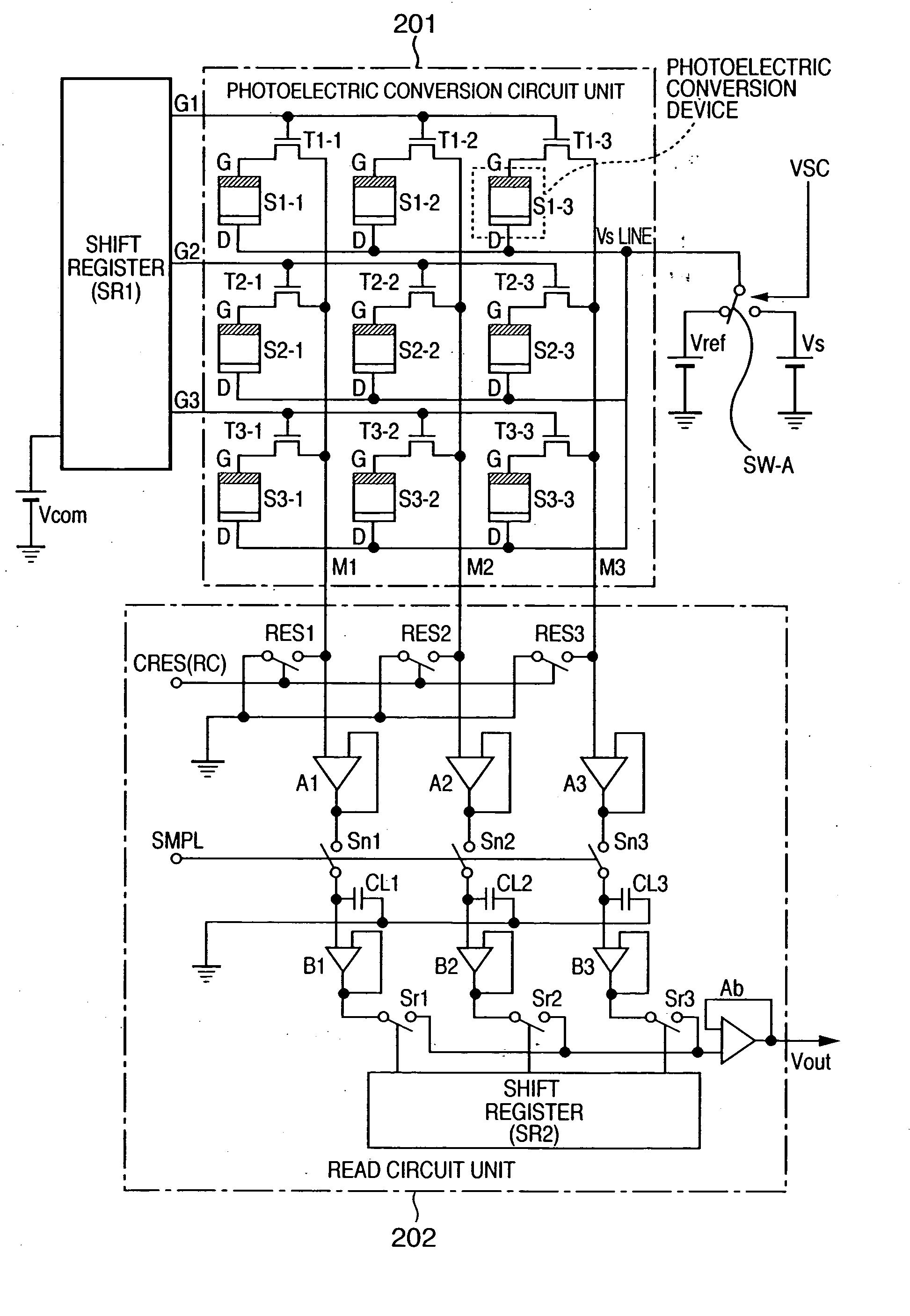
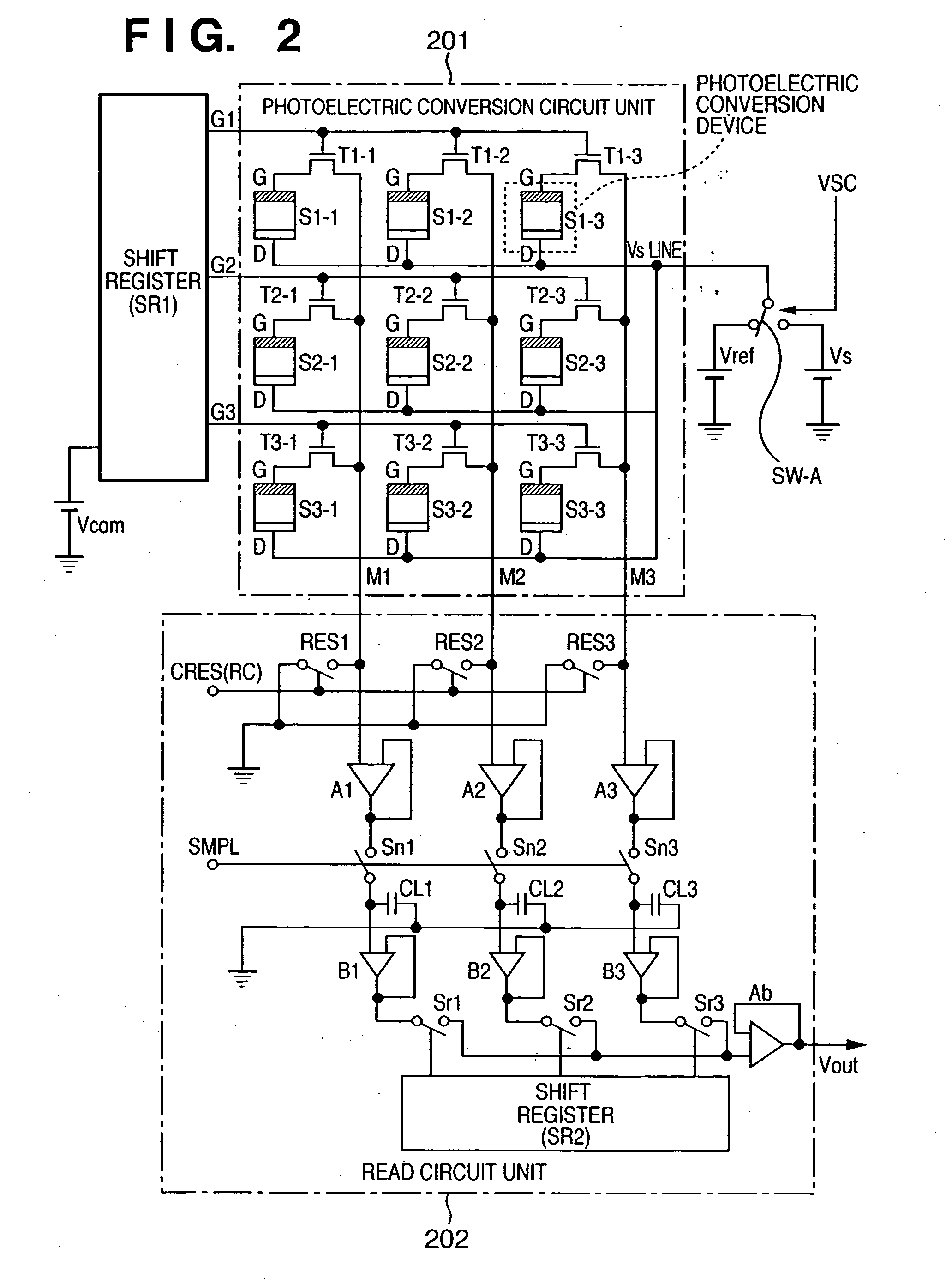
[0044] The photoelectric conversion circuit unit 201 and read circuit unit 202 will be explained. FIG. 2 is a circuit diagram showing the two-dimensional arrangements of the photoel...
second embodiment
[0077] The second embodiment of the present invention will be described. The second embodiment is different from the first embodiment in the method in which the image processor determines whether to perform refresh operation. FIG. 9 is a flowchart showing the method in which an image processor 204 determines whether to execute refresh in the second embodiment. FIGS. 10A to 10C are tables showing an example of image data output from an A / D conversion unit 203 to the image processor 204 and the progress of the process in the second embodiment. Note that FIG. 2 shows the layout of 3×3 pixels, but FIGS. 10A to 10C show an expanded layout of 8×8 pixels, similar to the first embodiment.
[0078] In the second embodiment, if image data is input to the image processor 204 (step S11), the image processor 204 converts 8×8 image data into 4×4 image data by averaging image data (step S12). More specifically, the average of 2×2 upper left pixels having addresses of (x=1, y=1) to (x=2, y=2) out of ...
third embodiment
[0083] The third embodiment of the present invention will be described. The first and second embodiments perform a process using all pixel data output from the photoelectric conversion device. The third embodiment allows the user to arbitrarily select a region necessary to determine refresh. FIGS. 11A to 11C are schematic views showing the operation of an X-ray imaging apparatus according to the third embodiment of the present invention.
[0084] When the chest of a human body undergoes X-ray imaging, an image as shown in FIG. 11A is displayed on a display 205. For this image, outputs in the lateral direction at the center are plotted to obtain a graph as shown in FIG. 11B. As shown in FIG. 11B, an output at a graph center 206 is low, and an output at a periphery 207 is high because of the following reason. The graph center 206 corresponds to an output of X-rays having passed through the imaged chest of the human body, and X-rays are absorbed by the chest of the human body, decreasing...
PUM
 Abstract
Description
Claims
Application Information