Optical polarization beam combiner/splitter

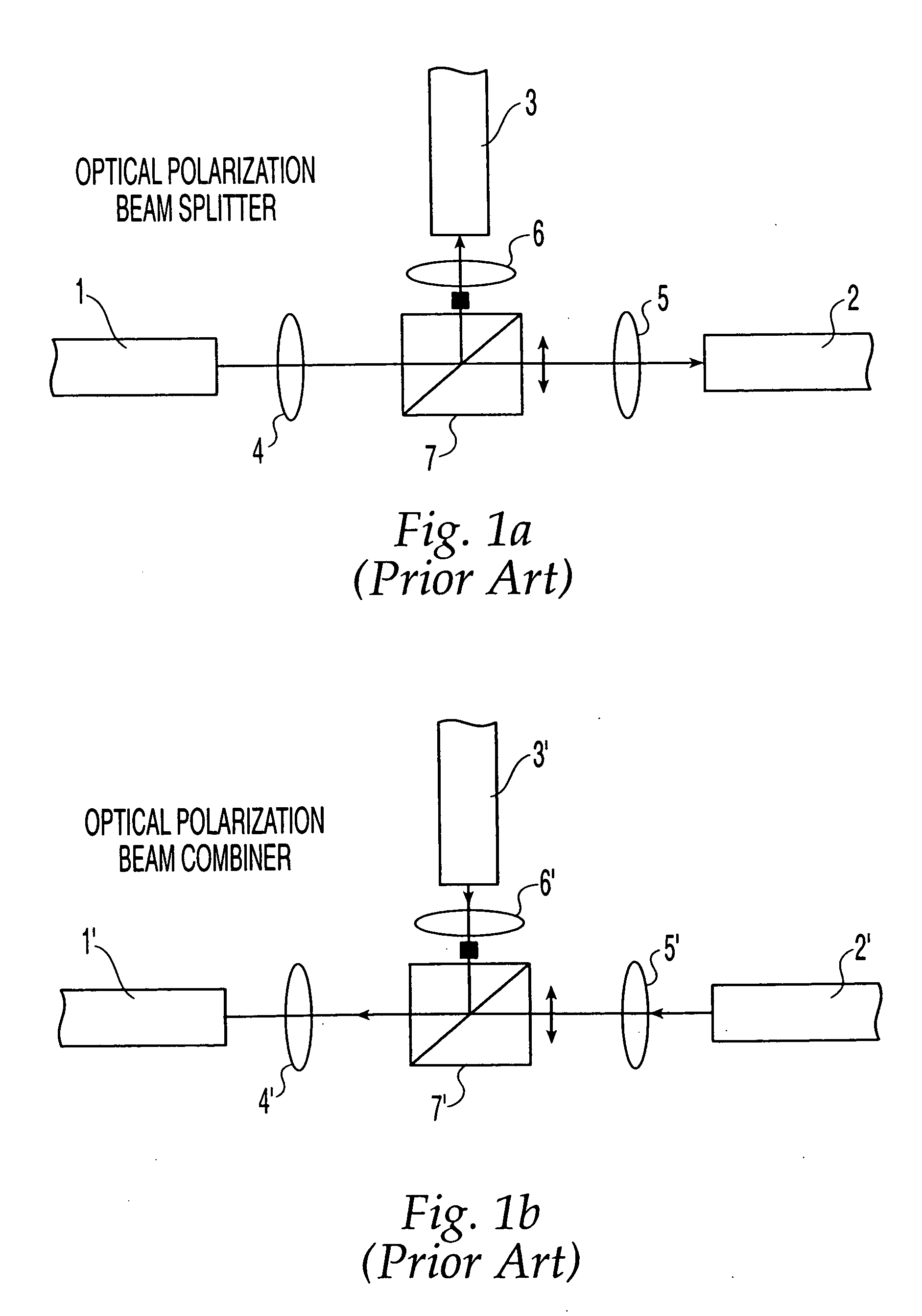
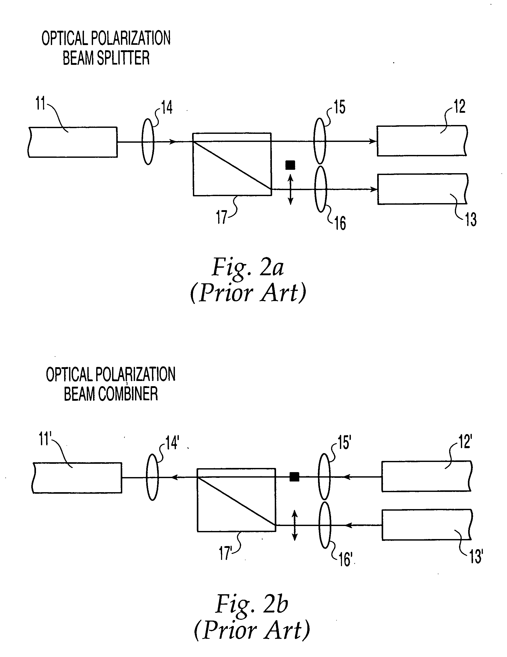
a technology combiner, which is applied in the field of optical polarization beam combiner/splitter, can solve the problems of extinction ratio, device of fig. 2a /i>and b>2/i>and b>2/i>and b>2/i>and b>2/i>and b>2/i>a /i>and

Inactive Publication Date: 2005-09-15
ABRAXIS BIOSCI LLC
View PDF94 Cites 21 Cited by
  • Summary
  • Abstract
  • Description
  • Claims
  • Application Information

AI Technical Summary

Benefits of technology

[0020] The use of a thin film wire-grid polarizer, a very thin optical element, enables the overall optical device to be compact and simpler than the prior art optical PBC / S devices. This simplified design will provide reduced insertion loss through the device, smaller footprint, simpler assembly, improved manufacturing yields, and thus reduced overall optical packaging cost.
[0021] Furthermore, the optical PBC / S device of the present invention also provides better optical performance over the prior art optical PBC / S because of the superior performance characteristics of thin film wire-grid polarizers. Thin film wire grid polarizers provide among other benefits, a broader wavelength range of operation and broader range of incidence angles.

Problems solved by technology

The prior art device depicted in FIGS. 1a and 1b, have several drawbacks, such as a large overall device size necessitated by the need to employ orthogonally disposed beams, and a low extinction ratio, which is a characteristic of polarization beam splitter cubes.
But, the device of FIGS. 2a and 2b tends to be bulky.
Another drawback of an optical PBC / S device employing a birefringent crystal is the relatively narrow range of incident angles the birefringent crystal can accommodate.
Such designs tend to be bulky, resulting in higher insertion loss.
Another drawback for this type of device is the need for a matching index coating for the dielectric film.
This is often implemented with an organic compound, which limits the overall power that the device can handle.
Fused fiber wave guides offer overall lowest insertion loss, but in most designs the two channels have different insertion losses and it is not easy to match them.
Another distinct drawback for the fused fiber wave guide polarization beam combiner is the very narrow wavelength range of operation.
Typically the range is a few nanometers and increasing the device bandwidth will result in increased insertion loss.

Method used


Image

  • Optical polarization beam combiner/splitter
  • Optical polarization beam combiner/splitter
  • Optical polarization beam combiner/splitter

Examples


Embodiment Construction

[0038] It is to be understood that the figures and descriptions of the present invention have been simplified to illustrate elements that are relevant for a clear understanding of the present invention, while eliminating, for the purpose of clarity, many other elements found in optical devices and methods of making the same. Those of ordinary skill in the art may recognize that other elements and / or steps are desirable and / or required in implementing the present invention. However, because such elements and steps are well known in the art, and because they do not facilitate a better understanding of the present invention, a discussion of such elements and steps is not provided herein. The disclosure herein is directed to all such variations and modifications to such elements and methods known to those skilled in the art.

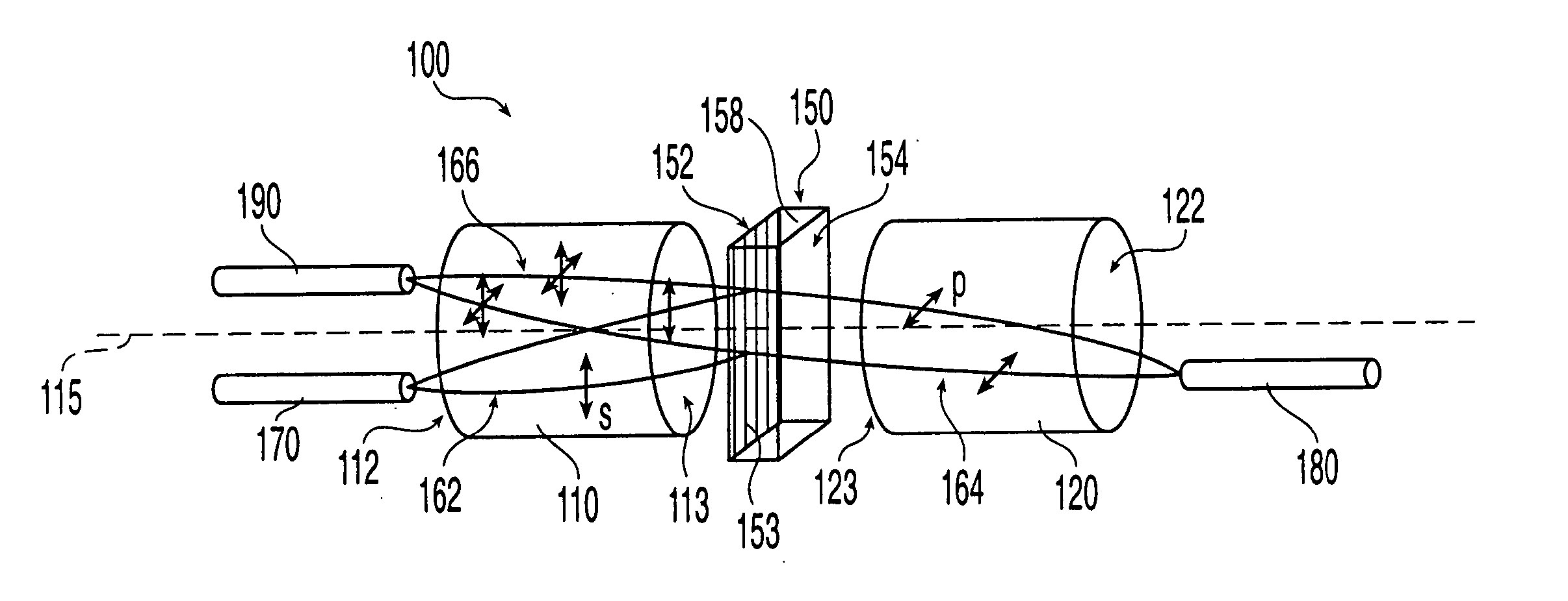
[0039]FIG. 4 illustrates a perspective view of an optical PBC / S device 100 according to an embodiment of the present invention. The optical PBC / S device according t...


PUM


Abstract

An optical device for combining two orthogonally polarized beams or splitting a beam into two orthogonally polarized beams is provided that utilizes two collimating / focusing lenses and a thin film wire-grid polarizer. Because the thin film wire-grid polarizer can be fabricated in very thin profile, the provision of a thin film wire-grid polarizer allows the optical polarization beam combiner / splitter device to be highly integrated and simultaneously realize a number of performance advantages of a thin film wire-grid polarizer over other types of polarizers utilized in various prior art polarization beam combiner / splitters.

Description

RELATED APPLICATIONS [0001] This application claims priority to U.S. patent application Ser. No. 10 / 158,025 entitled “Optical Polarization Beam Combiner / Splitter” in the name of inventors Anguel Nikolov and Stephen Chou filed May 30, 2002 under 35 U.S.C. 120 and incorporates this application by reference as if included herein in its entirety.FIELD OF THE INVENTION [0002] The present invention generally relates to optical polarization beam combiners / splitters and more particularly to packaged fiber-optic polarization beam combiners / splitters that utilize a thin film wire-grid polarizer. BACKGROUND OF THE INVENTION [0003] Optical polarization beam combiners / splitters are used in many optical communications applications including those that require amplification of optical signals, preferred distribution of the polarization states, a combination of both, or separation of beam polarizations. [0004]FIGS. 1a and 1b illustrate an example of a prior art optical polarization beam combiner / sp...

Claims


Application Information

Patent Timeline
Patent Type & Authority Applications(United States)
IPC IPC(8): G02B5/30G02B6/27G02B6/34
CPCG02B5/3058G02B6/2937G02B6/2773G02B6/272
Inventor NIKOLOV, ANGUELCHOU, STEPHEN Y.
Owner ABRAXIS BIOSCI LLC
Why Eureka
Try Eureka