Robotically guided catheter

a robotic guided and catheter technology, applied in the direction of catheters, instruments, packaged goods, etc., can solve problems such as deflection of the catheter tip

Active Publication Date: 2005-09-15
BIOSENSE WEBSTER INC
View PDF72 Cites 222 Cited by
  • Summary
  • Abstract
  • Description
  • Claims
  • Application Information

AI Technical Summary

Benefits of technology

[0045] In some embodiments of the present invention, the catheter comprises an automated catheter, adapted to be primarily robotically controlled. The control mechanism comprises an integrated robotic control mechanism, which comprises a plurality of puller wires, e.g., four. The puller wires are disposed about the circumference of the catheter and extend along its length, typically passing through respective lumens. The distal ends of the puller wires are attached at respective points in a vicinity of the distal end of the catheter, and the proximal ends of the wires are coupled to respective motors. The motors are able to tense and relax the respective puller wires. Typically, by selective activation of respective motors, the control mechanism is able to manipulate the distal end of the catheter through 360 degrees of deflection. Alternatively, the integrated robotic control mechanism comprises a steering mechanism that utilizes shape memory alloys (SMAs), electroactive polymers (EAPs), and / or ionic polymer metal composites (IPMCs).

Problems solved by technology

Lengthwise movement of the piston relative to the housing results in deflection of the catheter tip.

Method used


Image

  • Robotically guided catheter
  • Robotically guided catheter
  • Robotically guided catheter

Examples


Embodiment Construction

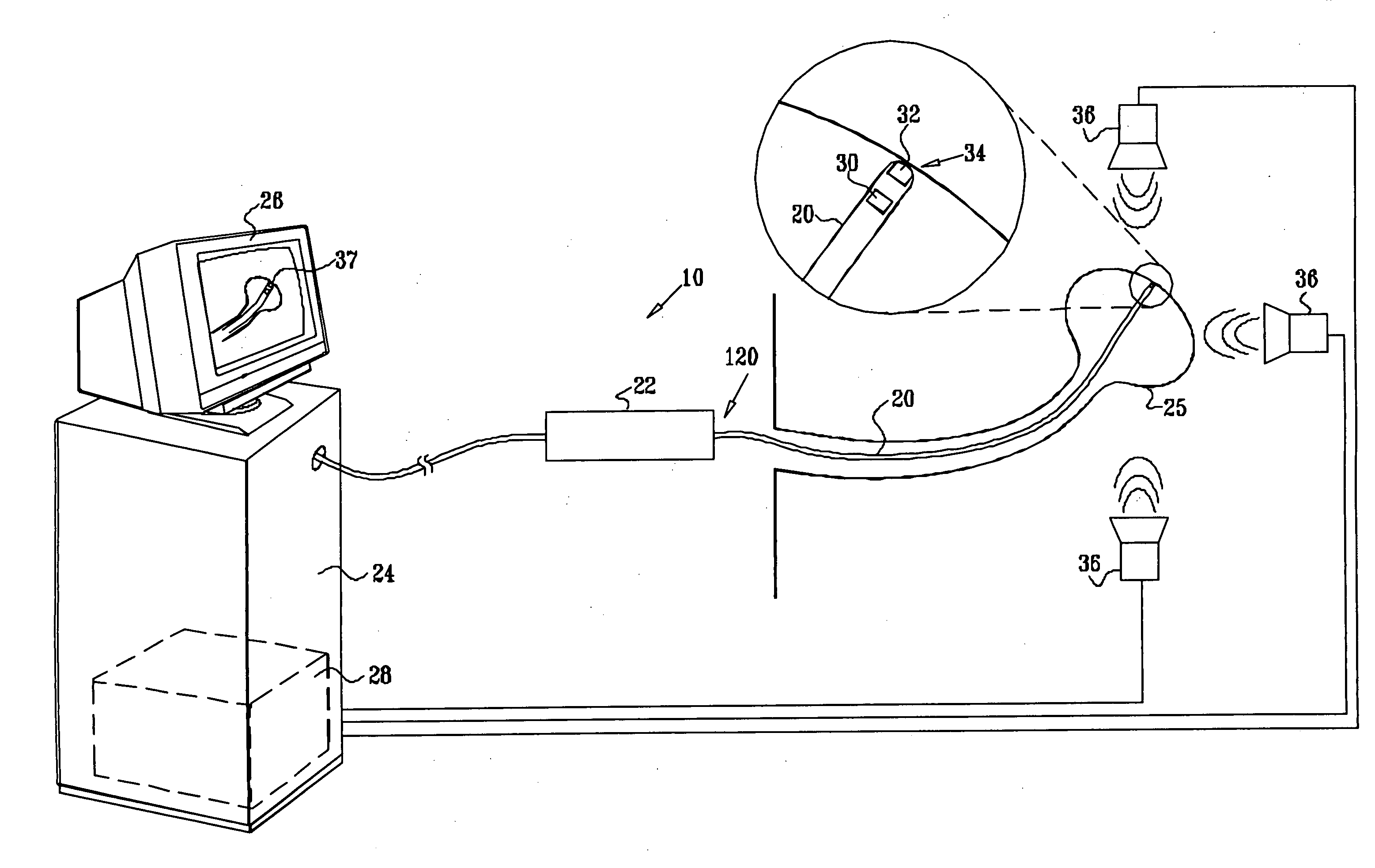
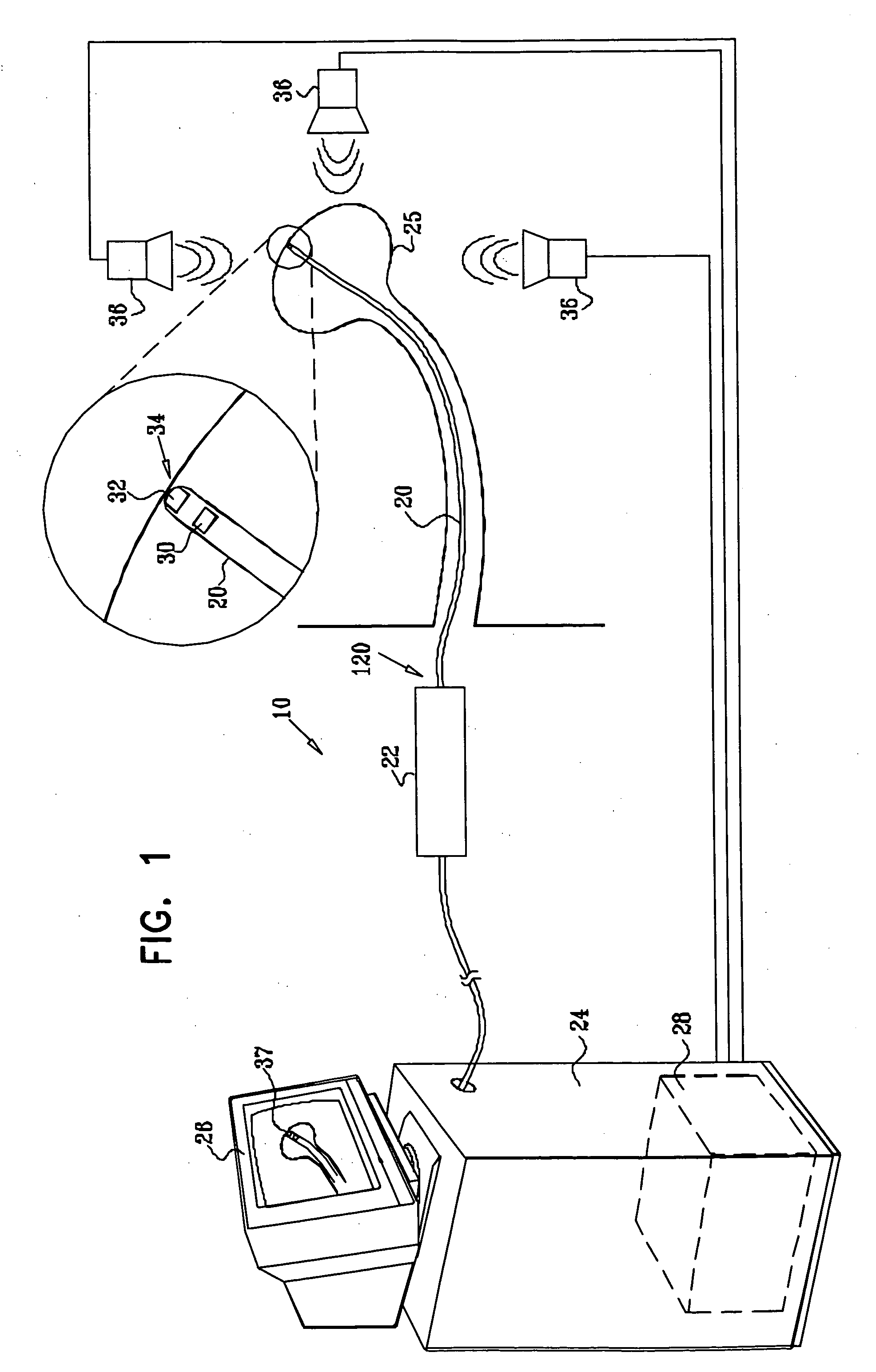
[0121]FIG. 1 is a schematic illustration of a robotic guided catheter system 10, in accordance with an embodiment of the present invention. Catheter system 10 comprises a catheter 20, a control mechanism 22, and a console 24. Catheter 20 is adapted to be inserted into an area of interest 25 of a subject, such as a body cavity (e.g., a heart) or a physiological lumen (e.g., a blood vessel or a digestive tract). Console 24 typically comprises a display monitor 26 and a computer 28. Computer 28 is programmed in software and / or hardware to carry out the functions described herein. This software may be downloaded to the computer in electronic form, over a network, for example, or it may alternatively be provided on tangible media, such as magnetic or optical media or other non-volatile memory. For some applications, computer 28 comprises a general-purpose computer.

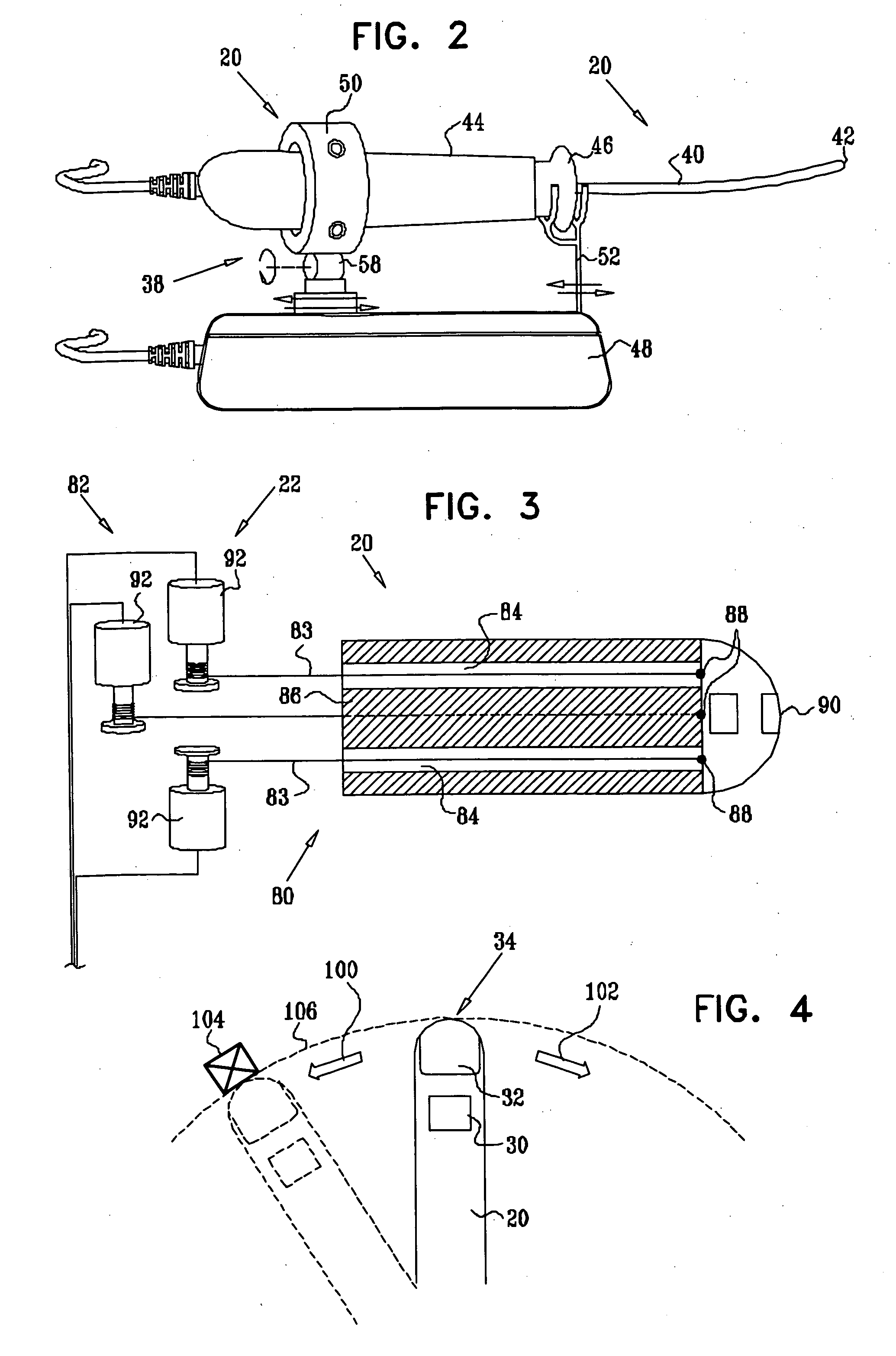
[0122] Catheter 20 typically comprises at least one position sensor 30 and at least one tool 32, both located in a vicinity ...


PUM


Abstract

Apparatus is provided for use with a steerable catheter that includes a thumb control adapted to control a deflection of a distal tip of the catheter. The apparatus includes a robot, including an end-effector, adapted to be coupled to the thumb control, and a controller, adapted to drive the end-effector to deflect the distal tip by manipulating the thumb control.

Description

FIELD OF THE INVENTION [0001] The present invention relates generally to invasive medical instruments, and specifically to methods and apparatus for manipulating and steering a catheter for diagnostic and therapeutic purposes. BACKGROUND OF THE INVENTION [0002] Mechanisms for moving, guiding and / or steering invasive medical instruments, such as catheters, in living tissue for therapeutic, diagnostic and surgical purposes are well known in the art. Technologies have been developed that enable locating and tracking medical devices inserted within the body, including determining the orientation of a point on the device, such as the tip of a catheter. Locating a surgical object within living tissue can be accomplished in a variety of ways, including using various forms of electromagnetic or ultrasound energy. Numerous catheter steering and deflection mechanisms are known in the art. [0003] U.S. Pat. No. 6,083,170 to Ben-Haim, which is assigned to the assignee of the present application ...

Claims


Application Information

Patent Timeline
Patent Type & Authority Applications(United States)
IPC IPC(8): A61B17/00A61B19/00A61M25/01
CPCA61B19/2203A61B19/5244A61B2017/003A61B2019/2211A61M2025/0058A61B2019/5251A61B2019/5272A61M25/0147A61M25/0158A61B2019/2242A61B2034/2072A61B34/20A61B34/71A61B2034/301A61B34/30A61B2034/2051A01G9/02A01G9/042A01G13/04A01K63/003B65D85/50
Inventor GOVARI, ASSAFALTMANN, ANDRES CLAUDIOEPHRATH, YARON
Owner BIOSENSE WEBSTER INC
Why Eureka
Try Eureka