
Air flow measuring device

Inactive Publication Date: 2005-09-22
HITACHI LTD +1
View PDF8 Cites 6 Cited by
  • Summary
  • Abstract
  • Description
  • Claims
  • Application Information

AI Technical Summary

Benefits of technology

[0003] The present invention provides a sub-passage that allows dust or moisture contained in the intake air, which may provide inaccurate readings by an air flow measuring element, due to contamination or break-down, to be separated by inertial force of the dust or moisture while ensuring a sufficient air flow in the area where the flow measuring element is installed.

Problems solved by technology

However, its cleaning effect is inadequate since the dust particles or moisture contained in the intake air, often passes through the filter element reaching the air intake passage, where the air flow measuring device is located.
Also, certain after market air filter products are poorer in quality as compared to the original product which further exasperates the problem.
If the dust particles contained in the intake air adheres to the flow measuring element of the air flow measuring device, the characteristic heat radiation which is utilized to accurately measure the air flow can deviate, outputting inaccurate results.
Also, depending on the dust particle size and speed of the particle in the incoming air flow, the flow measuring element may even be damaged.
Further, if moisture, such as water, adheres to the measuring element, the element may deteriorate with time due to sudden temperature changes or provide an inaccurate output due to changes in the heat radiation rate.

Method used


Image

  • Air flow measuring device
  • Air flow measuring device
  • Air flow measuring device

Examples


Embodiment Construction

[0021] Exemplary embodiment of the present invention will be described below in connection with the drawings. Other embodiments may be utilized and structural or logical changes may be made without departing from the spirit or scope of the present invention. Although the invention is described in terms of an automobile component, namely, an automobile engine, the invention is applicable to other combustion engines utilizing an air flow measuring device. Like items are referred to by like reference numerals throughout the drawings.

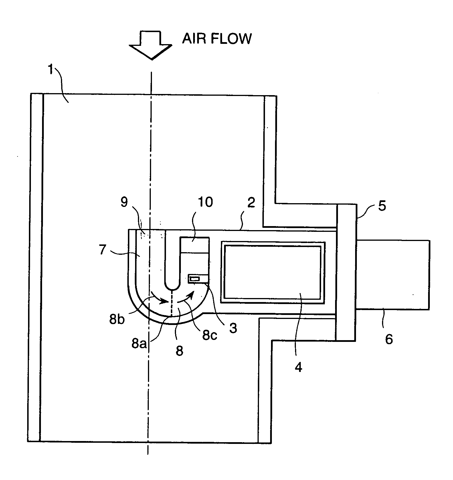
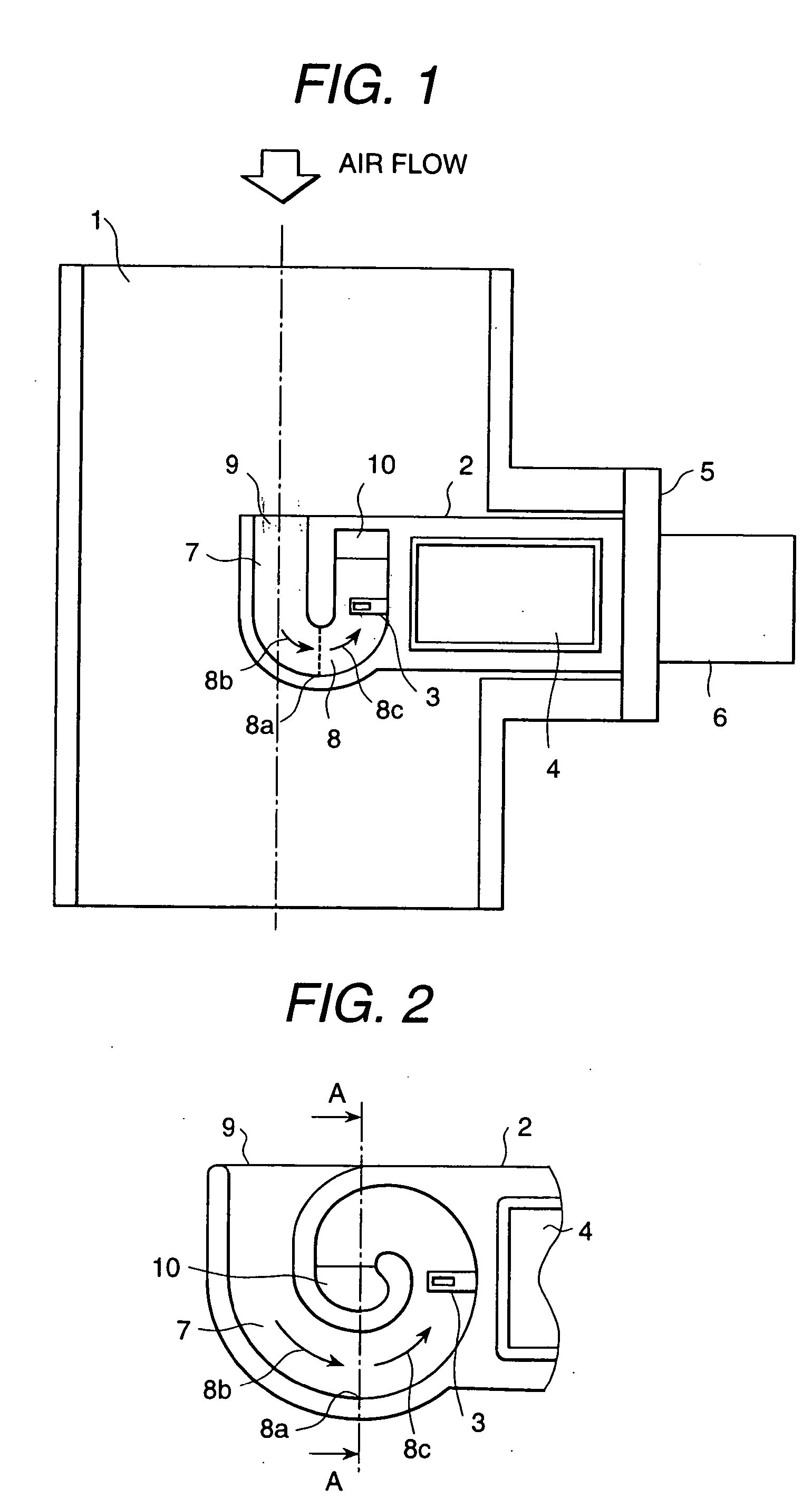
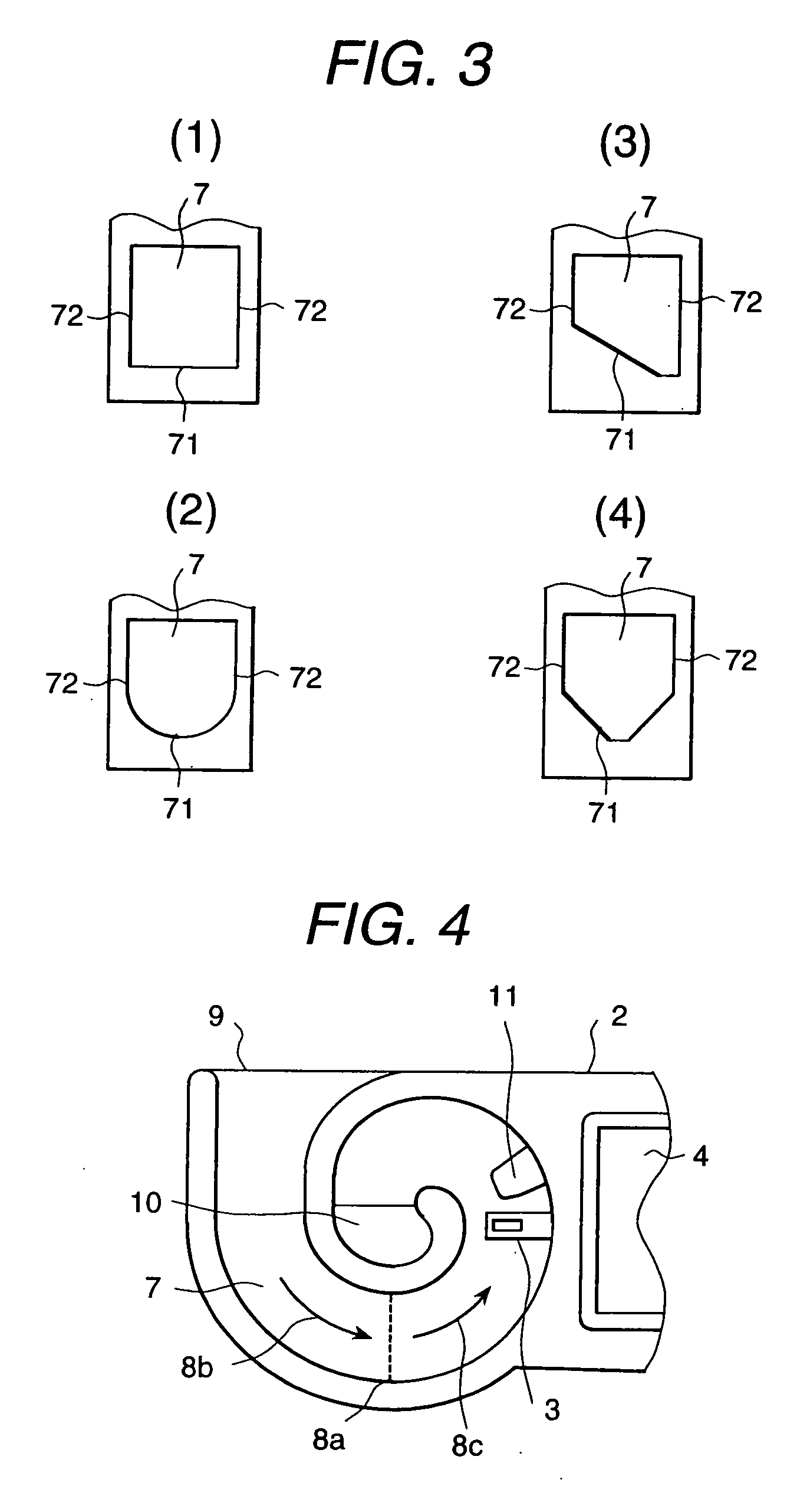
[0022] Referring now to the drawings, FIG. 1 illustrates a cross-sectional view of an air flow measuring device of the present invention. The air flow measuring device is preferably a heating resistor type. In an air intake passage 1 of an automobile internal combustion engine, a module housing 2 for a heating resistor type air flow measuring device is installed through a module flange 5. A sub-passage 7 is formed at the end of the module housing 2 and a f...


PUM


Abstract

The present invention provides an air flow measuring device comprising a housing with a sub-passage having a inlet and a outlet for air flow formed in the housing, the sub-passage further having a predefined curvature with a maximum downstream point and a flow measuring element located in the sub-passage at a position at least further downstream from the point.

Description

FIELD OF THE INVENTION [0001] The present invention relates to air flow measuring devices, and particularly, to air flow measuring devices for internal combustion engines. DISCUSSION OF THE RELATED ART [0002] Conventional air flow measuring devices for internal combustion devices are provided with a filter element for cleaning the incoming air. However, its cleaning effect is inadequate since the dust particles or moisture contained in the intake air, often passes through the filter element reaching the air intake passage, where the air flow measuring device is located. Also, certain after market air filter products are poorer in quality as compared to the original product which further exasperates the problem. If the dust particles contained in the intake air adheres to the flow measuring element of the air flow measuring device, the characteristic heat radiation which is utilized to accurately measure the air flow can deviate, outputting inaccurate results. Also, depending on the ...

Claims


Application Information

Patent Timeline
IPC IPC(8): F02D35/00G01F1/684G01F5/00G01F15/12
CPCG01F1/6842G01F15/12G01F5/00G01F1/6845
Inventor KIKAWA, HIROMUWATANABE, IZUMIIGARASHI, SHINYANAKADA, KEIICHIUEYAMA, KEI
Owner HITACHI LTD
Learn More