

Draping product having an adhesive edge for surgical interventions
- Summary
- Abstract
- Description
- Claims
- Application Information
AI Technical Summary
Benefits of technology
Problems solved by technology
Method used
Image

Examples
Embodiment Construction
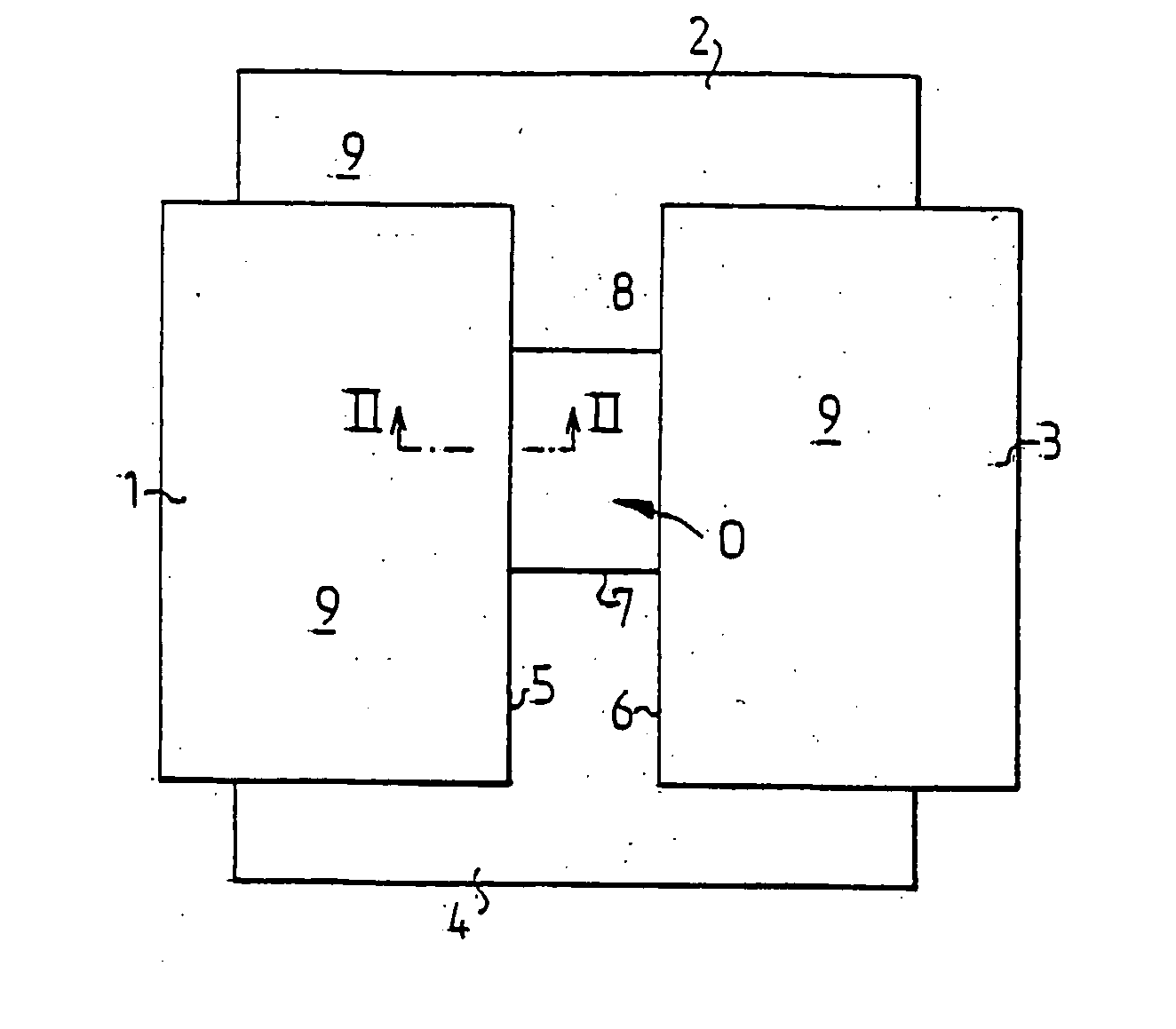
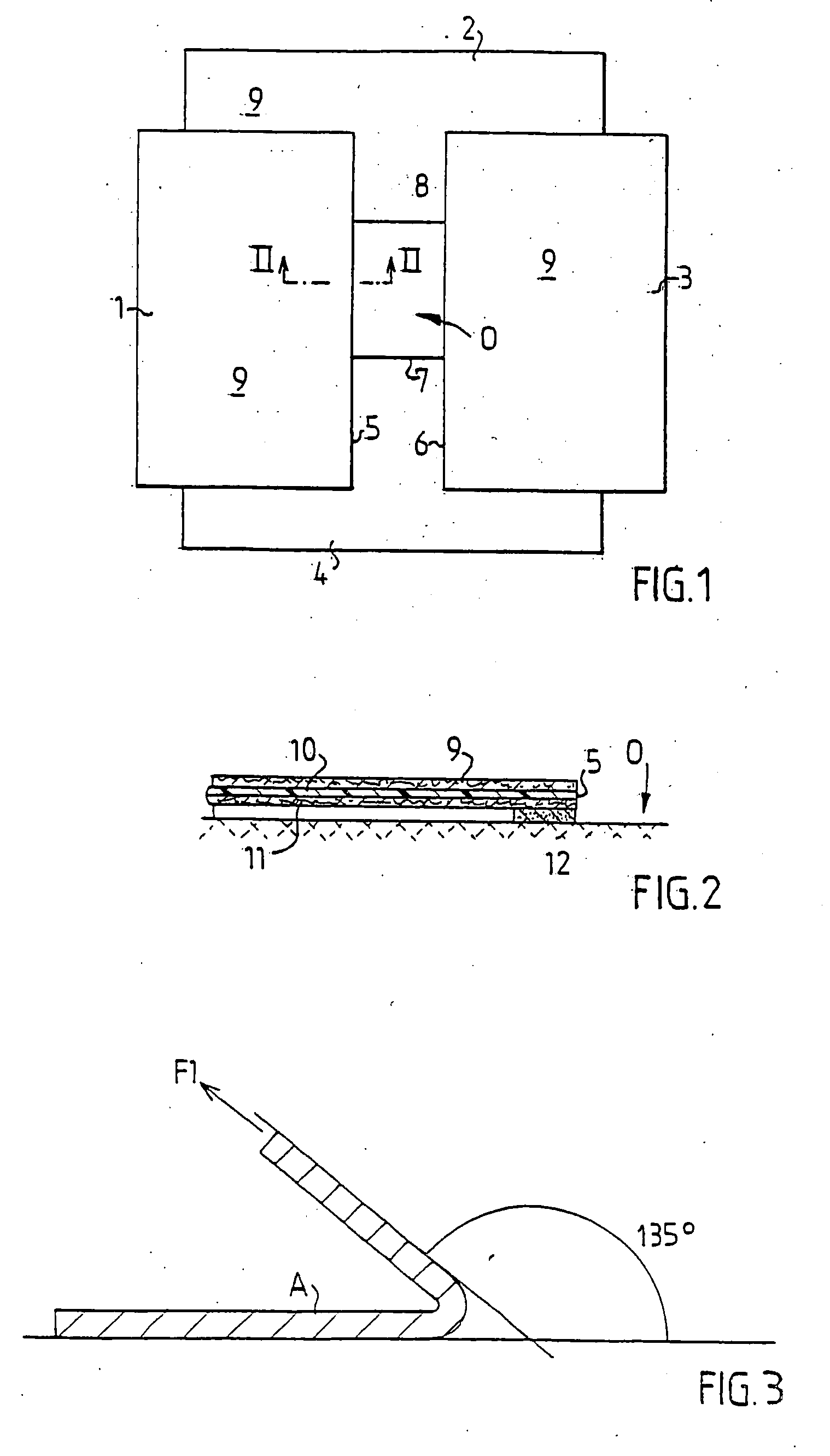
[0020] In FIG. 1 is schematically shown a draping system comprising four draping products 1-4, two surgical drapes 2 and 4 and two surgical towels 1 and 3, applied around an operative area O on a patient not shown in the figure. Draping products 1 and 3 delimit two opposite, parallel edges 5,6 of the operative area and the draping products 2 and 4 delimit two opposite, parallel edges 7,8 being perpendicular to the edges 5,6. In order to prevent liquid from the operative area from flowing under the edges 5-8 or bacteria from the area outside the operative area from penetrating into the operative area, the edges 5-8 are adhesively affixed to the skin of the patient.
[0021] The draping products 1-4 may advantageously be surgical drapes and surgical towels denoted Klinidrape® from Mölnlycke Health Care AB, Sweden, consisting of a laminate of three layers, a liquid absorbing top layer 9 of nonwoven, a liquid-tight middle layer 10 of polyethylene and a lower absorbent layer 11 of cellulos...
PUM
 Abstract
Description
Claims
Application Information