
Collapsible shelter having a reinforced truss and telescoping leg

a collapsible shelter and telescopic technology, applied in the field of collapsible shelters, can solve the problems of difficult folding and unfolding of frames, unsightly sagging of overlying canopy, and many other problems of collapsible shelters, and achieve the effects of strengthening the structure, enhancing the structural frame, and easy folding

Inactive Publication Date: 2005-09-22
OPAC LLC +1
View PDF10 Cites 25 Cited by
  • Summary
  • Abstract
  • Description
  • Claims
  • Application Information

AI Technical Summary

Benefits of technology

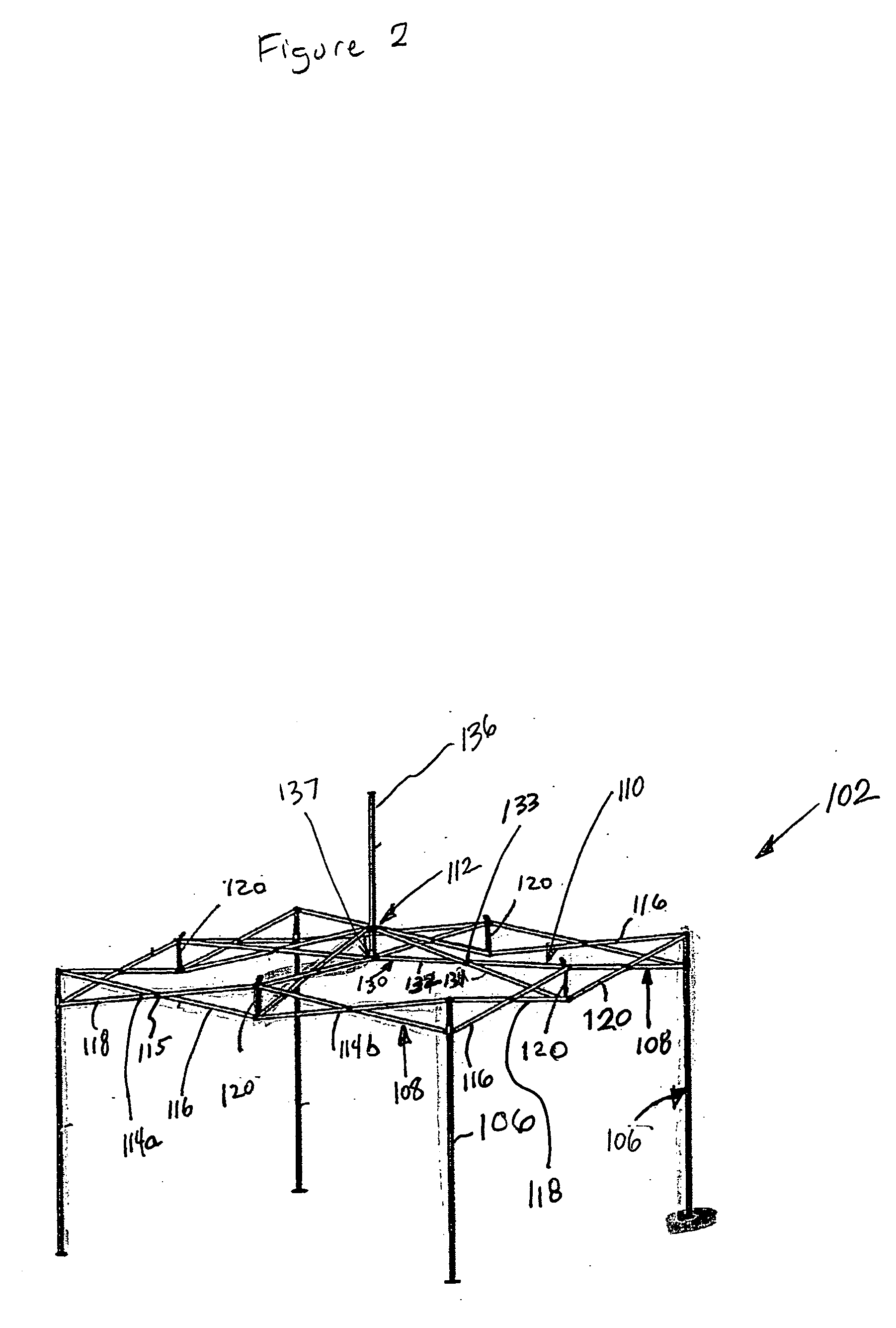
[0012] The collapsible shelter as described above possesses several advantages. By selectively coupling the cross pieces of the various scissor units, the structure can be strengthened while still allowing for easy folding into a compact configuration. Such a structure therefore incorporates the advantage of scissor-type linkages while overcoming the disadvantages. Further, the coupling of the scissor unit to both the center post and the eave assembly allows the a center post to both maintain the canopy cover taut and also enhance the structural frame.

Problems solved by technology

However, several problems associated with collapsible shelters have been observed.
The frames tend to be difficult to fold and unfold, unstable, somewhat large when folded, and prone to breakage.
Some prior shelter frames also allow the overlying canopy to sag in an unsightly manner.
While the scissor-type linkages provide an easily folded frame, users often suspend items from the linkages or even rest hands thereon resulting in distortion and / or breakage of the structure.
However, the '726 structure does not possess the ease of folding seen with the scissor-type linkages.
Such prior art footings prevent easy folding and unfolding of the structure 10 because of edges that catch upon or even dig into the support surface during folding.

Method used


Image

  • Collapsible shelter having a reinforced truss and telescoping leg
  • Collapsible shelter having a reinforced truss and telescoping leg
  • Collapsible shelter having a reinforced truss and telescoping leg

Examples


Embodiment Construction

[0030] The present invention overcomes many of the prior art problems associated with collapsible shelters. The advantages, and other features of the system disclosed herein, will become more readily apparent to those having ordinary skill in the art from the following detailed description of certain preferred embodiments taken in conjunction with the drawings which set forth representative embodiments of the present invention and wherein like reference numerals identify similar structural elements.

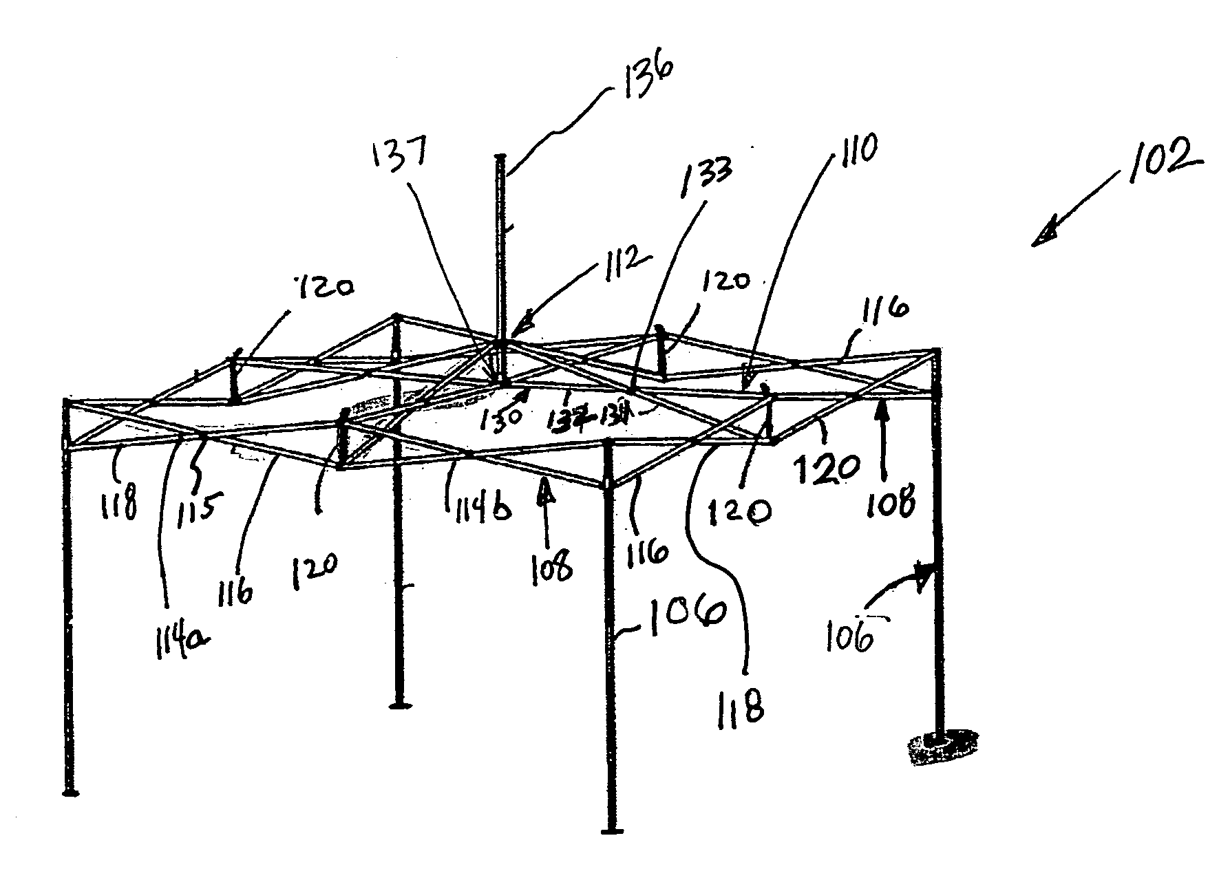
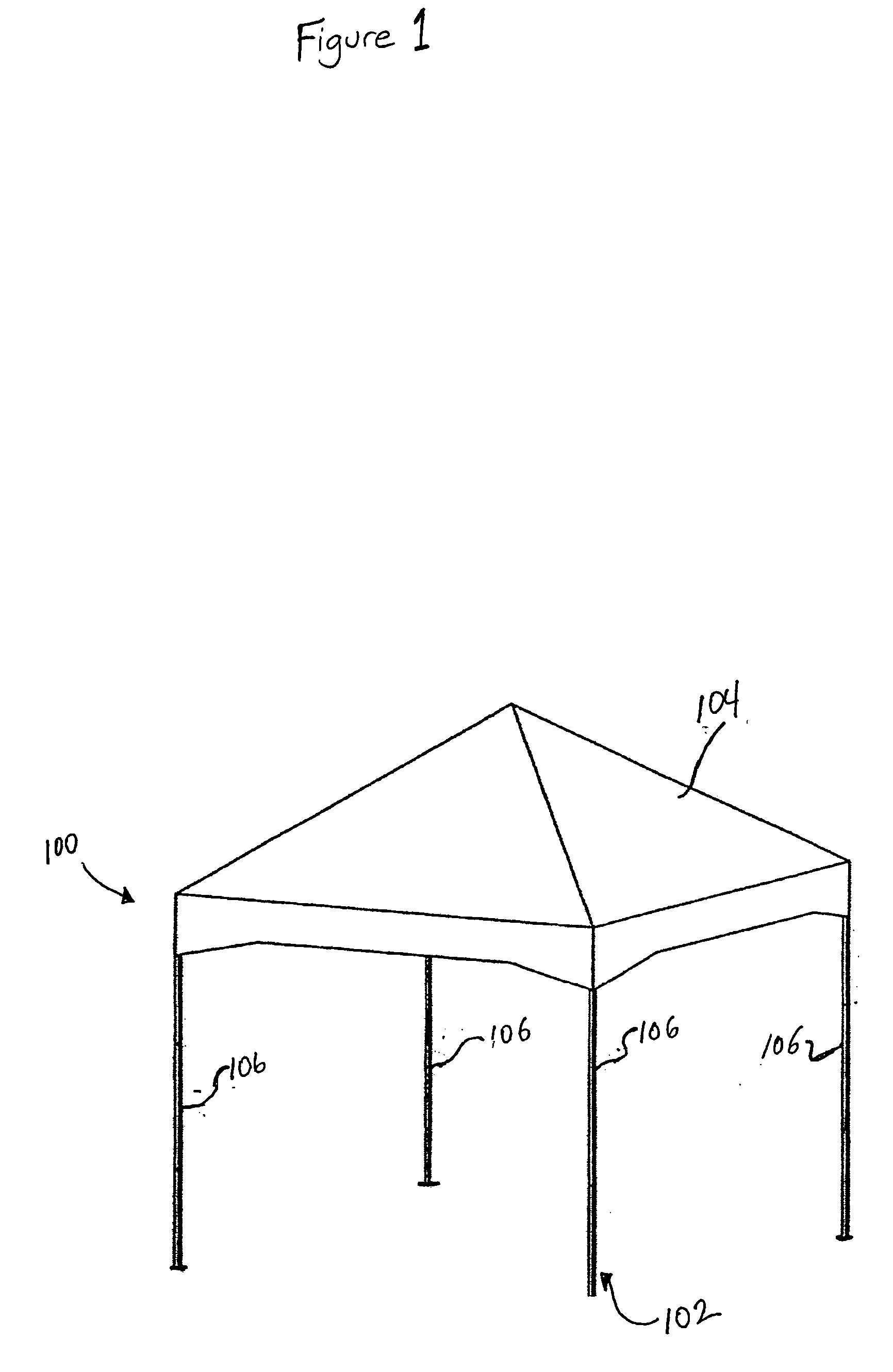
[0031] Referring to FIG. 1, a shelter 100 in accordance with the present disclosure includes a collapsible frame assembly 102 for mounting a canopy 104 thereon. The collapsible frame 102 is shown in the raised, unfolded or “set-up” position. The collapsible frame 102 includes four leg assemblies 106 adapted to rest on a support surface. It should be understood that a shelter 100 according to the subject disclosure may include more or less than four leg assemblies 106 to form configuratio...


PUM


Abstract

A collapsible shelter has a canopy supported by legs and a center post. The legs and center post are rigidly fixed in position by eave and truss assemblies made from scissor type linkages. The ends of the scissor type linkages can be coupled to create a robust frame assembly. A locking button fixes the scissor linkages to the center post and a strap couples secures the interconnections between scissor linkages. The legs telescope in a non-binding manner and include curved footings for easy assembly and disassembly.

Description

CROSS-REFERENCE TO RELATED APPLICATIONS [0001] This application claims priority to Chinese Patent Application No. 200420020981.8, filed Mar. 17, 2004, Chinese Patent Application No. 200420020986.0, filed Mar. 17, 2004, Chinese Patent Application No. 200420021066.0, filed Mar. 19, 2004, and Chinese Patent Application No. 200420021142.8, filed Mar. 22, 2004, each of which is incorporated herein by reference. BACKGROUND OF THE INVENTION [0002] 1. Field of the Invention [0003] The subject disclosure relates generally to shelters, and more particularly to an improved shelter having a collapsible frame. Even more particularly, the subject disclosure relates to a shelter including a canopy supported by a cable mounted on a collapsible frame. [0004] 2. Background of the Related Art [0005] Over the years, many tents and other shelters having collapsible frames have been introduced. Such structures are commonly used to provide shelter during camping trips, picnics, parties, military operation...

Claims


Application Information

Patent Timeline
Patent Type & Authority Applications(United States)
IPC IPC(8): E04H15/28E04H15/38E04H15/50
CPCE04H15/50
Inventor GOLDWITZ, BRIAN L.
Owner OPAC LLC
Learn More