Tyre self-sealing device for the wheel of a vehicle

a self-sealing device and vehicle technology, applied in the direction of tyre parts, tyre-inflating valves, tyre measurements, etc., can solve the problems of valve and connection, both problematic and uncertain wheel balancing operations, and tire inflation, so as to prevent the valve from being deteriorated, quick and easy disassembly of the valve, the effect of improving reliability and li

Inactive Publication Date: 2005-09-22
SYEGON
View PDF0 Cites 63 Cited by
  • Summary
  • Abstract
  • Description
  • Claims
  • Application Information

AI Technical Summary

Benefits of technology

[0026] A first advantage of the present invention lies in the fact that the tire pressure is maintained even when the wheel or the valve have been dismounted.
[0027] Another advantage lies in the possibility of performing balancing operations without the tricky dismounting of the valve, balancing being carried out by any type of apparatus.
[0028] Another advantage lies in the quick and easy dismounting of the valve after dismounting the wheel.
[0029] Yet another advantag

Problems solved by technology

The drawback to this system in the case of light vehicles lies firstly in the fact that operations to dismount the wheel and/or the valve always result in the deflation of the tire, thereby making wheel balancing operations both problematic and uncertain.
Another drawback lies in the fact that the valve and its connection remain accessible from the exterior and are subject to theft and deliberate deterio

Method used


Image

  • Tyre self-sealing device for the wheel of a vehicle
  • Tyre self-sealing device for the wheel of a vehicle
  • Tyre self-sealing device for the wheel of a vehicle

Examples


Embodiment Construction

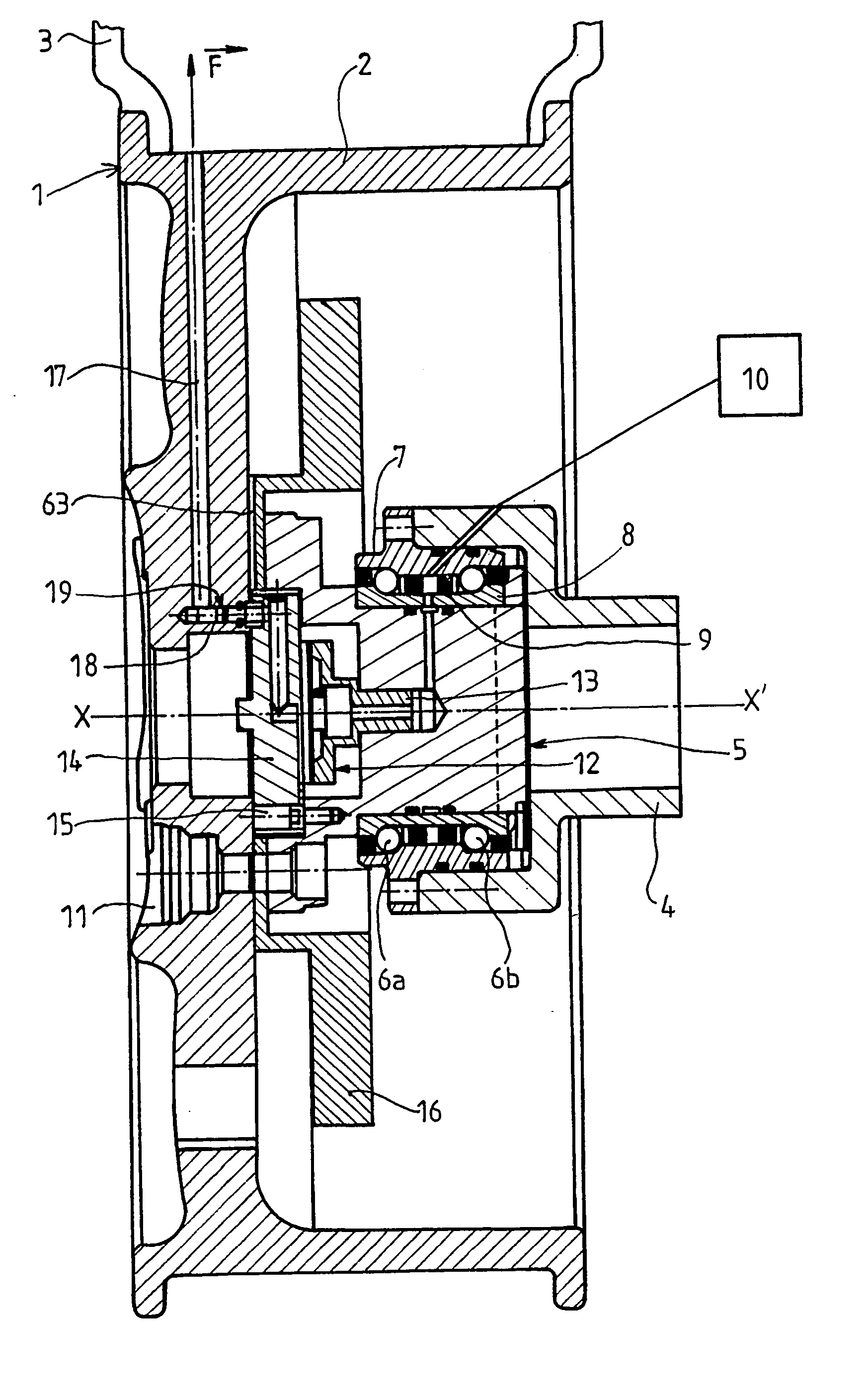
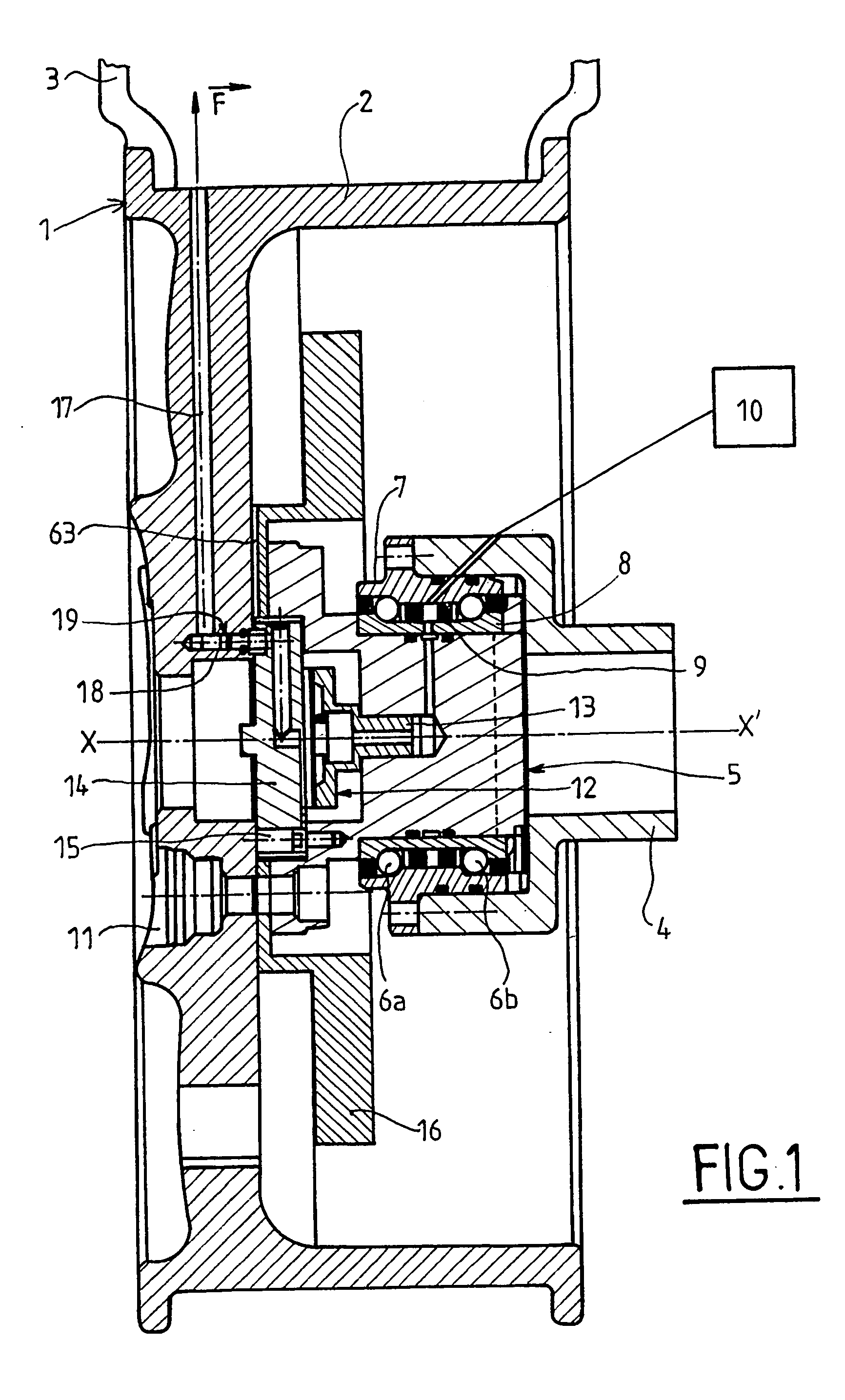
[0040]FIG. 1, which represents a section of a wheel mounted on its drive shaft, shows the wheel 1 constituted of a wheel rim 2 and a tire 3. The wheel rim 2 is connected to its support shaft 4 by means of a hub 5. Two bearings 6a and 6b are classically positioned between the shaft 4 and the hub 5. These bearings classically comprise an external housing 7 and an internal housing 8 between which is placed a revolving joint 9 to allow pressurised fluid to pass between an external source 10 and the tire 3 as will be explained hereafter in reference to FIG. 2. The wheel rim 2 is classically mounted on the hub by means of bolts whose housing 11 can be seen in the Figure. A valve 12 is mounted in the hub 5 and according to the invention comprises a valve bonnet 13 screwed into the hub and a seat 14, the valve being indexed with respect to the hub by means of a screw 15. This screw allows the valve 12 to be indexed with respect to the hub to ensure the continuity of the fluid circuit as wil...


PUM


Abstract

A self-sealing device for a tire on a vehicle wheel, including a wheel, a wheel hub supporting the wheel, a wheel supply circuit, an inflating and deflating valve for supplying compressed air from a pressurized circuit, wherein the valve is positioned between the wheel and the wheel hub and includes sealing means integrated into the wheel supply circuit, wherein the sealing means is activatable to an open position in the presence of the valve and to a closed position in the absence of the valve.

Description

BACKGROUND OF THE INVENTION [0001] 1. Field of Invention [0002] The technical scope of the present invention is that of inflation and deflation systems for a vehicle wheel. [0003] 2. Description of the Related Art [0004] The principle of valves enabling the inflation and deflation of vehicle tires by remote control is known, notably by patents FR-2667826 and FR-2731655. [0005] In the scope of application above-mentioned, it is known for the valve system to be particularly well adapted to heavy equipment, such as lorries, military vehicles, public works or civil security vehicles. This system has to be adapted when applied to light vehicles. [0006] The drawback to this system in the case of light vehicles lies firstly in the fact that operations to dismount the wheel and / or the valve always result in the deflation of the tire, thereby making wheel balancing operations both problematic and uncertain. The user or the constructor is thus obliged to install an isolating valve to avoid ha...

Claims


Application Information

Patent Timeline
IPC IPC(8): B60C23/00
CPCF16C41/005B60C23/003B60C23/00318B60C23/00345B60C23/00354B60C23/00363
Inventor MAQUAIRE, MICHELADRION, DAVID
Owner SYEGON
Why Eureka
Try Eureka