Pulsed rotation screw removal and insertion device

a screw and insertion device technology, applied in the direction of motor/generator/converter stopper, dynamo-electric converter control, manufacturing tools, etc., can solve the problems of screw itself breaking, screw head or shank having a higher torque, screw head being stripped, etc., to reduce the amount of required pressure, prevent the stripping of the screw head, and reduce the occurrence of stripped screws

Inactive Publication Date: 2005-09-22
BOGUE EDWARD M
View PDF10 Cites 46 Cited by
  • Summary
  • Abstract
  • Description
  • Claims
  • Application Information

AI Technical Summary

Benefits of technology

[0014] 1: A reduction in occurrence of stripped screws heads.
[0015] 2: A reduction in required pressure on the screwdriver bit against the screw head in order to prevent the stripping of screw heads.
[0016] 3: A...

Problems solved by technology

The reversal time should be sufficient to allow the screwdriver bit to be reinserted into the screw head, but not sufficient time to rotate the screw significantly backwards.
The screw head or shank can have a higher torq...

Method used


Image

  • Pulsed rotation screw removal and insertion device
  • Pulsed rotation screw removal and insertion device
  • Pulsed rotation screw removal and insertion device

Examples


third alternative embodiment

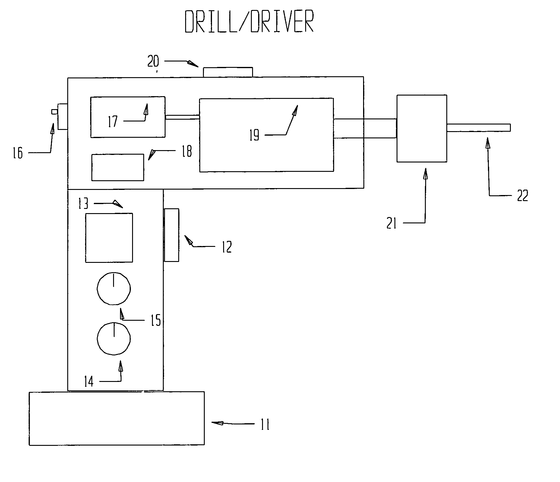
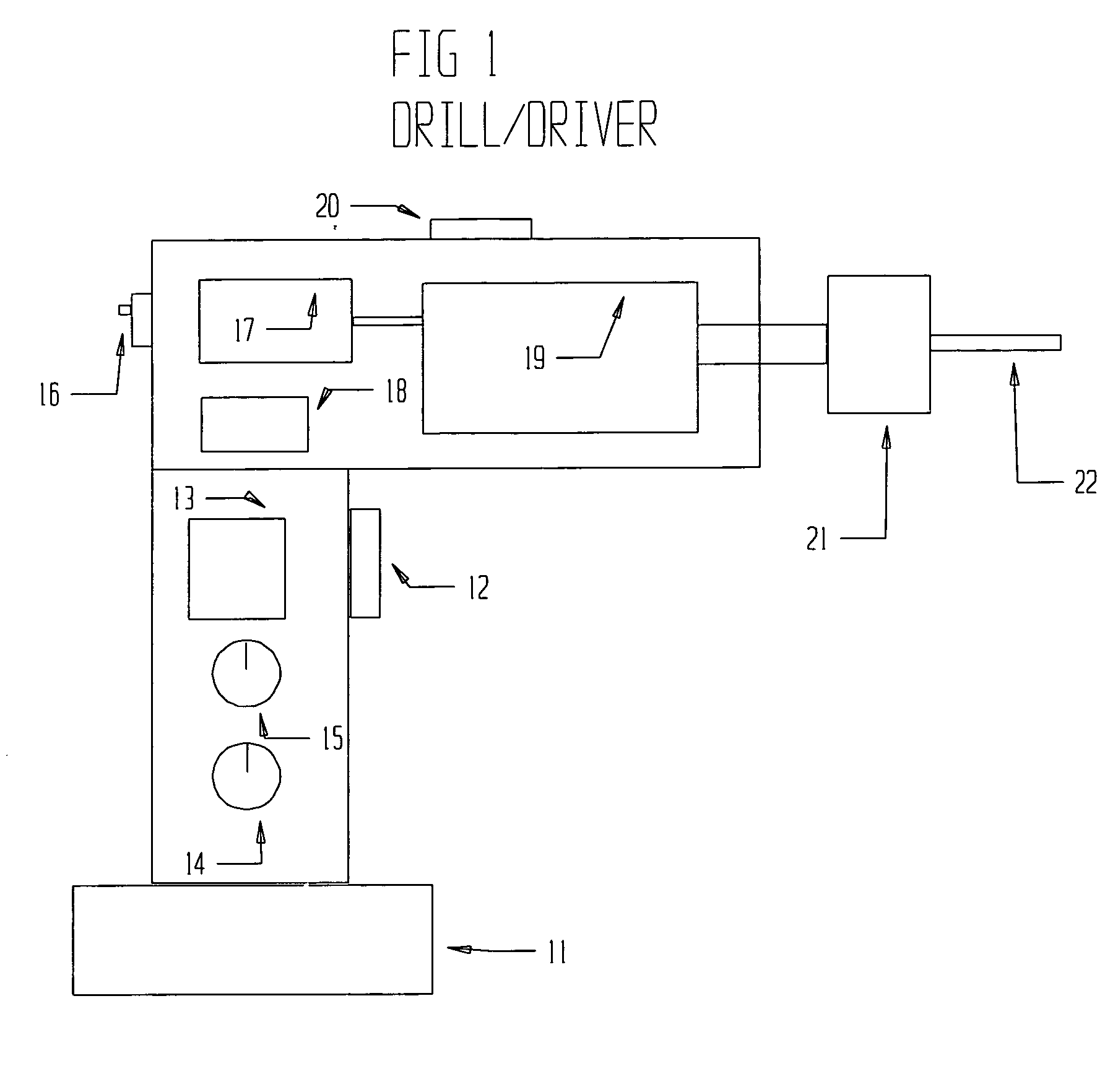
[0076] The pulsed momentary reversals can be accomplished through mechanical means in some cases. This can be implemented in the drill / driver assembly or external to the drill / driver, for example in the chuck mechanism. One way of implementing this mechanically would be to use a planetary gear set between the input and output of the chuck. The output of the chuck would turn at a slower rate than the input. This speed differential allows a means for internally counting revolutions of the chuck, and a means to power the reversal stroke. The reversal stroke can be implemented by using a spring and an impact weight to force the reversal. This could be further simplified by causing a periodic momentary disengagement rather than a reversal of the output shaft. The disengagement method would not be as effective in avoiding stripped screw heads, but may have a decreased cost of production. The mechanical design could also be implemented inside the drill / driver using a mechanical revolution ...


PUM


Abstract

A drill/driver (e.g. an electric drill) with a screwdriver bit attachment, and a method of controlling the drill/driver, are described. This method of control will greatly reduce the occurrence of stripped screw heads on most types of screws. By periodically stopping insertion of a screw and reversing direction of the screwdriver bit, the screwdriver bit will be reinserted fully back into the screw head. By ensuring the screwdriver bit is always fully inserted in the screw head, the stripping of a screw head will be prevented. This can be easily implemented on most types of powered screwdrivers including the most common device used for screw insertion on a construction job site, the cordless drill/driver.

Description

CROSS-REFERENCE TO RELATED APPLICATIONS [0001] Not Applicable STATEMENT REGARDING FEDERALLY SPONSORED RESEARCH OR DEVELOPMENT [0002] Not Applicable STATEMENT REGARDING FEDERALLY SPONSORED RESEARCH OR DEVELOPMENT [0003] Not Applicable BACKGROUND OF INVENTION [0004] This invention relates to power tools used to insert screws, specifically an improved drill / driver design to reduce the occurrence of stripped screws. BACKGROUND [0005] The invention has particular reference to hand-held and bench-mounted power screwdrivers and power drills with a screwdriving facility, and which are referred to as “drill / drivers” herein. [0006] The invention has particular reference to fasteners with threads. These fasteners include screws, bolts, or any fastener which require rotation of a driving device for installation, and which are referred to as “screws” herein. [0007] Many different screw head designs have been made to avoid the problem of stripped heads; square drive heads, hex heads, and torque h...

Claims


Application Information

Patent Timeline
IPC IPC(8): B25B15/00B25B21/00B25B21/02B25B23/147B25D1/00
CPCB25B21/00B25B23/147B25B21/02
Inventor BOGUE, EDWARD M.
Owner BOGUE EDWARD M
Why Eureka
Try Eureka