Electronic balance

a technology of electronic balance and magnetic force, applied in the direction of weighing apparatus using counterbalance, weighing apparatus details, instruments, etc., can solve the problems of reducing the stability of weight measurement, poor response, fluctuation in weight measurement, etc., to eliminate the impact of weight measurement, reduce vibration, and quick stop swaying

Inactive Publication Date: 2005-09-22
SHIMADZU CORP
View PDF7 Cites 17 Cited by
  • Summary
  • Abstract
  • Description
  • Claims
  • Application Information

AI Technical Summary

Benefits of technology

[0010] The electronic balance of the present invention is constructed as above, and when vibration imparted longitudinally along the balance beam, or horizontally intersecting perpendicularly with the longitudinal vibration, is transmitted to the balance beam, the braking force of the magnet damper or the air damper counteracts such vibration. As a result, the balance beam quickly stops swaying, reducing the vibration and eliminating the impact on the weight meas

Problems solved by technology

However, the electronic balance is known to generate errors in weight measurements in the case such that the balance beam 26 cannot establish a balance because the balance beam 26 i

Method used


Image

  • Electronic balance
  • Electronic balance
  • Electronic balance

Examples


Embodiment Construction

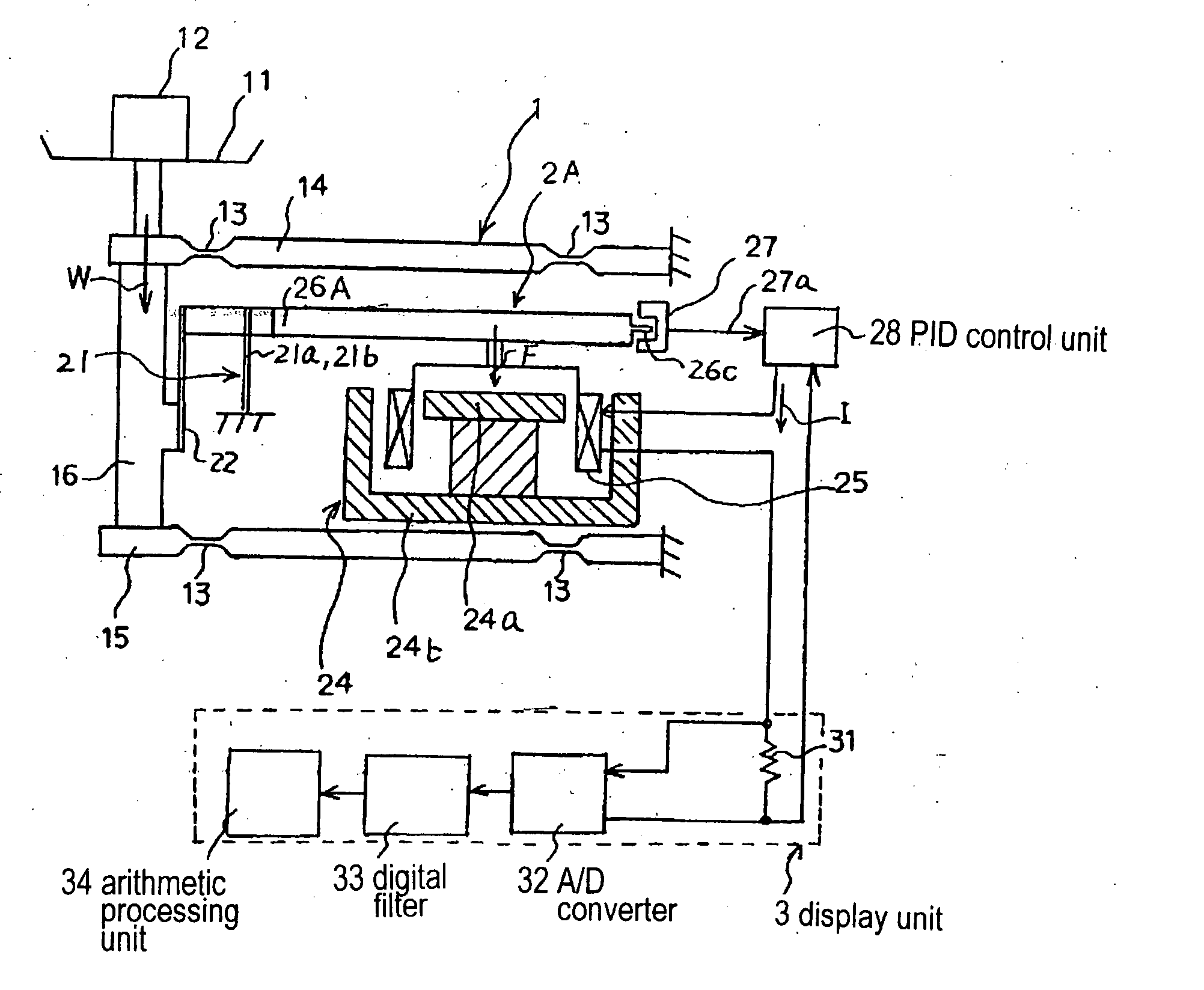
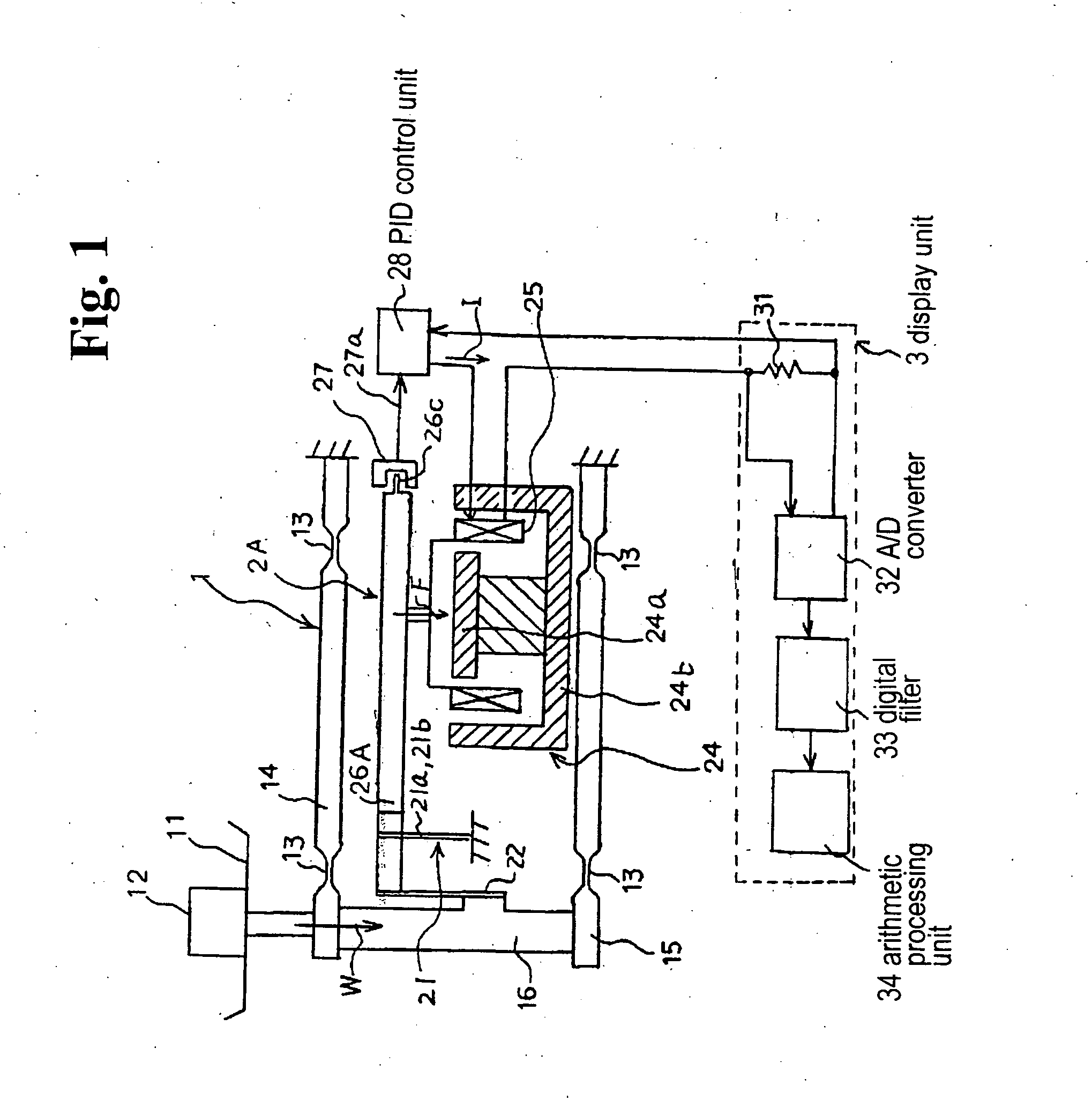
[0018] In the following, the electronic balance according to the present invention will be explained in detail by referring to an embodiment. FIG. 1 is a schematic view illustrating the construction of the electronic balance according to the present invention, FIG. 2(a) is a plan view depicting the construction of a balance beam 26A in the embodiment, and FIG. 2(b) is a side view of the same.

[0019] The electronic balance according to the present invention is constructed in the same manner as a conventional electronic balance with respect to the components other than the balance beam 26A depicted in FIGS. 2(a) and 2(b).

[0020] In other words, the electronic balance in this embodiment is comprised of a load transmission mechanism 1, which transmits the load placed on the pan W of the object 12 to be weighed and placed on weighing pan 11 as a vertical load; a load balancing mechanism 2, which balances the aforementioned load placed on the pan W transmitted via the load transmission me...


PUM


Abstract

An electronic balance includes a load transmission mechanism for receiving an object to be measured, a magnetic field generator having a force coil for generating magnetic field, and a balance beam connected at one end to the load transmission mechanism and disposed adjacent to the magnetic field generator with a fulcrum interposed between a portion connected to the weight section and the magnetic field generator. An electromagnetic force generated by supplying current to the force coil is applied to the balance beam to obtain a weight of the object from the current flowing through the force coil in equilibrium with the load. A damper is attached to the balance beam to control vibration in at least one of a longitudinal direction of the balance beam and a horizontal direction perpendicularly intersecting therewith.

Description

BACKGROUND OF THE INVENTION AND RELATED ART STATEMENT [0001] The present invention relates to an electromagnetic force balancing type electronic balance that measures weight of a load by balancing the load with electromagnetic force imparted to a balance beam, with a fulcrum interposed therebetween, and particularly relates to an electronic balance having short fulcrum intervals or a high-precision electronic balance. [0002]FIG. 6 depicts a conventional electromagnetic force balancing type electronic balance. This electronic balance is provided with a load transmission mechanism 1, which is composed of two beam members 14, 15 and a movable column 16 that transmits the load of an object 12 to be weighed placed on a weighing pan 11 in a vertical direction; a balance beam 26, one end of which is connected to said movable column 16 and the other end being provided with a force coil 25 generating electromagnetic force when control current flows through suspended therefrom, fulcrum 21 bei...

Claims


Application Information

Patent Timeline
IPC IPC(8): G01G7/04G01G23/06G01G23/10
CPCG01G23/10G01G7/04
Inventor IIDUKA, ATSUSHISHIMAUCHI, KUNIO
Owner SHIMADZU CORP
Why Eureka
Try Eureka