Drum brake and brake shoe for one such brake

a technology of drum brakes and shoes, which is applied in the direction of mechanically actuated brakes, fluid actuated drum brakes, brake elements, etc., can solve the problems of reducing therefore the stability of the vehicle, and the replacement of the drum brake shoe is complicated and the braking torque stability is improved. , the effect of improving the stability of the braking

Active Publication Date: 2005-09-22
ROBERT BOSCH GMBH
View PDF4 Cites 17 Cited by
  • Summary
  • Abstract
  • Description
  • Claims
  • Application Information

AI Technical Summary

Benefits of technology

[0007] An object of the invention is above all to provide a drum brake in which shoe replacement is simplified, while braking torque stability is improved.

Problems solved by technology

However, replacing a drum brake shoe when its friction lining is worn requires a relatively long disassembly and reassembly operation to be performed.
Because of the way forces exerted in the drum brake are distributed during braking, the shoe is subjected to a roll-up phenomenon that can reduce the stability of the braking and therefore the stability of the vehicle.
The fact that the braking force and the reaction force are applied at the same point tends to give rise to shoe roll-up.

Method used


Image

  • Drum brake and brake shoe for one such brake
  • Drum brake and brake shoe for one such brake
  • Drum brake and brake shoe for one such brake

Examples


Embodiment Construction

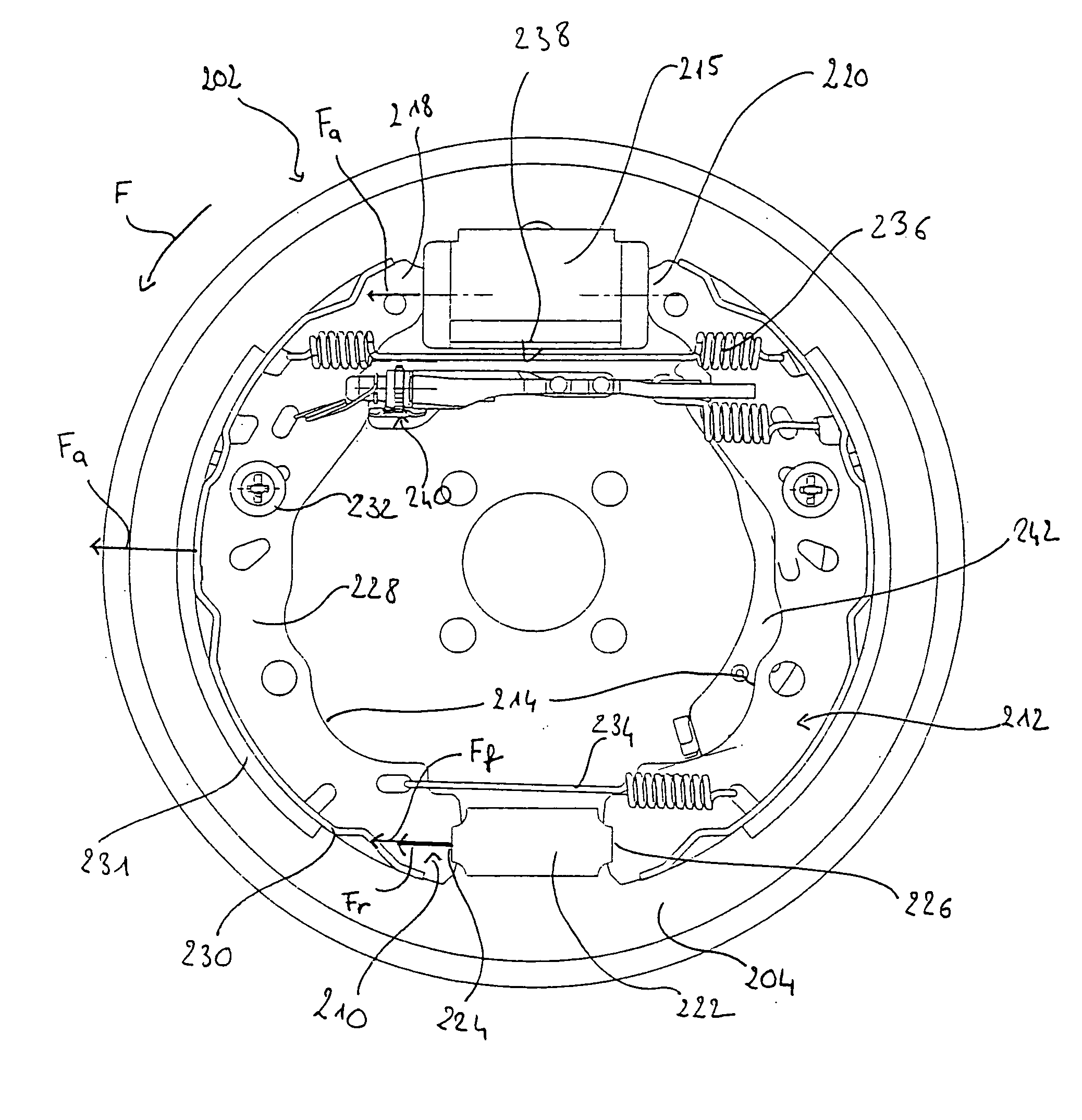
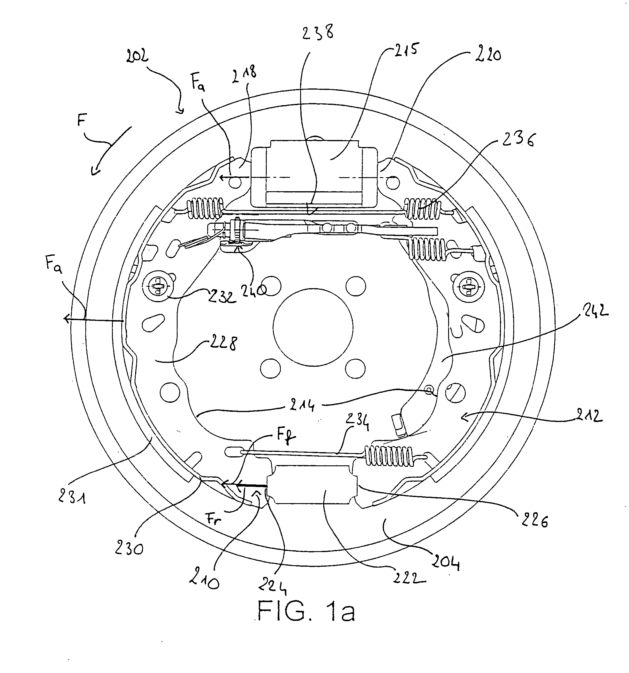
[0032]FIG. 1a shows a drum brake 202 of known type including a disk-shaped plate 204 organized to be fixed to a wheel arm of a vehicle, first and second shoes 210, 212 that are substantially circular arcuate in shape and that are mounted on the plate, their convex portions 214 facing towards the outside of the plate, and their convex portions 216 facing each other, a wheel cylinder 215 secured to the plate 204 and disposed between respective first ends 218, 220 of the first and second shoes 210, 212, and abutment means 222 secured to the plate 204 and disposed between second ends 224, 226 of the first and second shoes, and a drum (not shown) secured to the wheel and surrounding the convex portions 214 of the shoes 210, 212 with clearance.

[0033] Since the first and second shoes 210, 212 are symmetrical, only the first shoe is described below, while also specifying what is specific to it relative to the second shoe 212.

[0034] The first shoe 210 comprises a crescent-shaped rim 228, a...


PUM


Abstract

A drum brake comprising a plate on which at least one shoe having a friction lining is mounted. A lever moves the shoe against a wheel drum in response to a braking command to effect a brake application. A resilient return spaces the shoe apart from the drum when braking ceases. The shoe is mounted to slide along an essentially radial axis between two guide walls secured to the plate The lever for applying the shoe bears against the inside wall of the shoe for exerting a substantially radial force.

Description

[0001] The invention relates to a drum brake including a plate on which at least one shoe provided with a friction lining is mounted, application means for applying the shoe against a wheel drum in response to a braking command transmitted by a wheel cylinder, and resilient return means for spacing the shoe apart from the drum when braking ceases. BACKGROUND OF THE INVENTION [0002] Conventional-type drum brakes include an abutment that is fixed or that moves relative to the plate to which a first end of the shoe is fixed, which first end is opposite from a second end in contact with the wheel cylinder, the wheel cylinder transmitting the braking command directly to the shoe which is mounted to pivot relative to the plate at its end fixed to the abutment. [0003] Drum brakes offer several advantages over disk brakes. For the same application force, the braking torque is generally larger in a drum brake than in a disk brake. The “handbrake” function is easier to install on a drum brake...

Claims


Application Information

Patent Timeline
Patent Type & Authority Applications(United States)
IPC IPC(8): F16D51/14
CPCF16D51/14
Inventor DUPUIS, VINCENT
Owner ROBERT BOSCH GMBH
Why Eureka
Try Eureka