Power converter for a hybrid power filter

Active Publication Date: 2005-09-22
ABLEREX ELECTRONICS CO LTD
View PDF8 Cites 14 Cited by
  • Summary
  • Abstract
  • Description
  • Claims
  • Application Information

AI Technical Summary

Benefits of technology

[0012] The primary objective of this invention is to provide a power converter for a hybrid power filter. The power converter permits a power line of a power system to directly connect or connect through a passive power filter to a positive or negative terminal of a DC side of the power converter for free control of power electronic switches. When the power converter is applied to a single-phase power system, only a single-arm configuration for power electronic switch set (i.e. two power electronic switches) of the power converter is provided. When the power converter is applied to a three-phase, three-wire power system, only a double-arm configuration for power electronic switch set (i.e. four power electronic switches) of the power converter is provided. When the power converter is applied to a three-phase, four-wire power system, only a triple-arm configuration for power electronic switch set (i.e. six power electronic switches) of the power converter is provided. Consequently, the power converter can reduce the number of the power electronic switches.

Problems solved by technology

Theses electric power facilities may generate a large amount of harmonic current due to the nonlinear input characteristic of such loads.
The harmonic current will pollute the power system and results in the serious problems such as transformer overheat, rotary machine vibration, degrading voltage quality, electric power components destruction, medical equipment malfunction etc.
However, the passive power filter causes the problems of resonance and neighboring harmonic current injection that may destruct the passive power filter.
Additionally, it is quite hard to obtain a better filtering effect of the passive power filter due to system reactance that may affect the filtering characteristic of the passive power filter.
Therefore, the capacity and manufacture cost of the power converter 81 of the active power filter 8 must be significantly increased that limits the wide application of the active power filter 8.

Method used


Image

  • Power converter for a hybrid power filter
  • Power converter for a hybrid power filter
  • Power converter for a hybrid power filter

Examples


Embodiment Construction

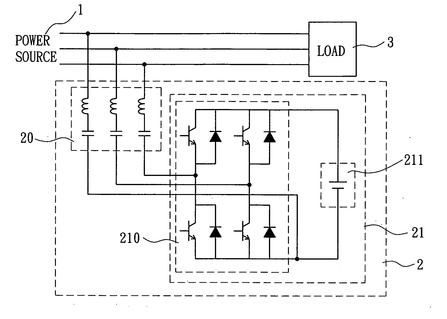
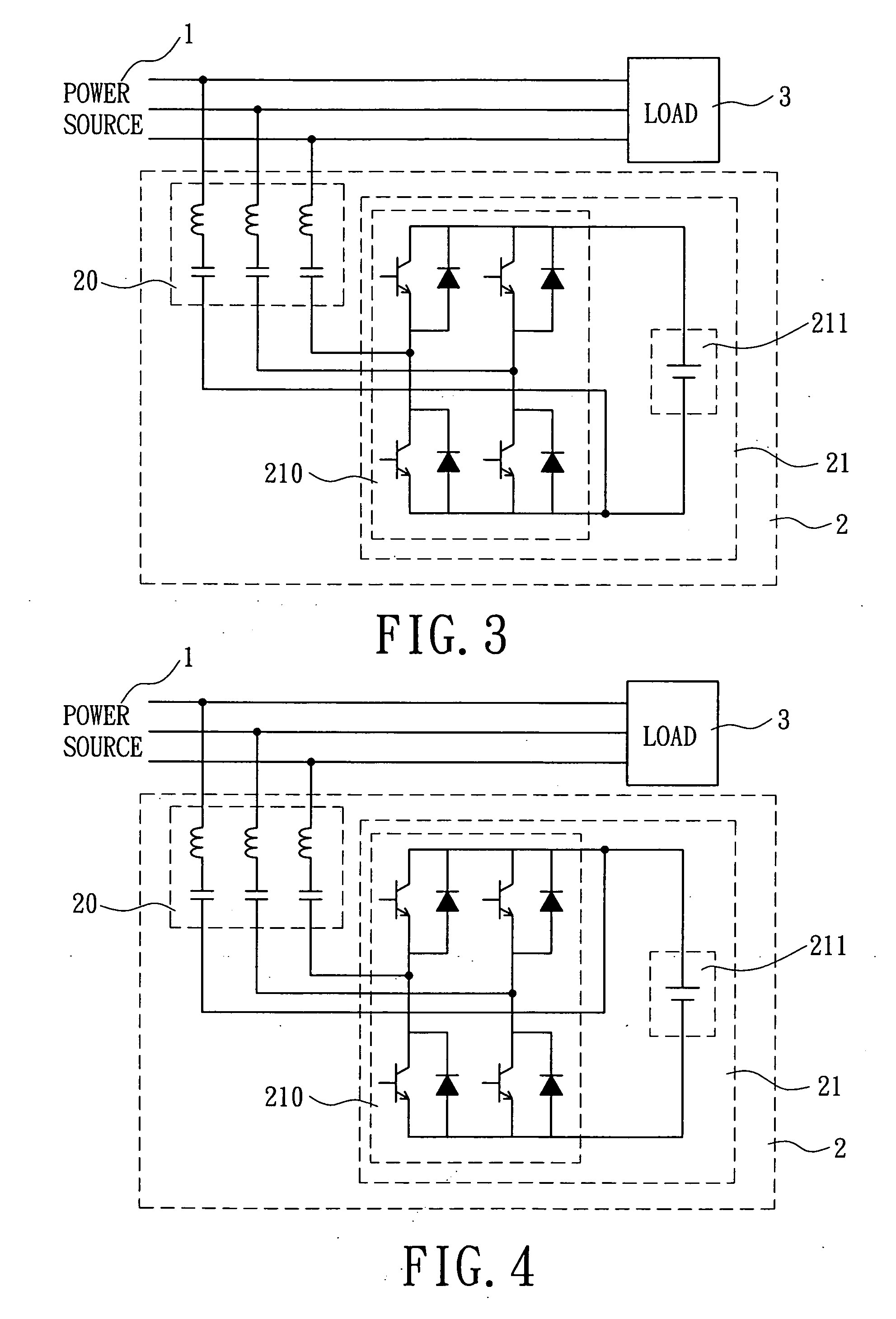
[0023] Referring to FIG. 3, it illustrates a schematic circuitry of a power converter of a hybrid power filter in accordance with a first embodiment of the present invention applied to a three-phase, three-wire power system. A power source 1 of the three-phase, three-wire power system supplies a three-phase, three-wire power to a load 3. A hybrid power filter 2 electrically connects to the load 3 in parallel, and filters harmonic currents generated from the load 3.

[0024] Referring again to FIG. 3, in the illustrated first embodiment, the hybrid power filter 2 is applied to the three-phase, three-wire power system. Generally, the hybrid power filter 2 consists of a passive power filter 20 and a power converter 21 serially connected thereto. The passive power filter 20 includes one or more three-phase single-tuned harmonic filter connected each other. The single-tuned harmonic filter consists of an inductor and an AC capacitor. The three-phase single-tuned harmonic filter is selectiv...


PUM


Abstract

A power converter for a hybrid power filter includes a power electronic switch set and a DC capacitor. The power converter permits a power line of a power system to directly connect or connect through the passive power filter to a positive or a negative terminal of the DC capacitor of the power converter for free control of the power electronic switches. Consequently, the power converter has a lesser number of the power electronic switches that can reduce the manufacture cost.

Description

BACKGROUND OF THE INVENTION [0001] 1. Field of the Invention [0002] The present invention relates to a power converter for a hybrid power filter. More particularly, the present invention relates to the hybrid power filter adapted to filter harmonic current which is generated from a single-phase power system, a three-phase, three-wire power system or a three-phase, four-wire power system. [0003] 2. Description of the Related Art [0004] Recently, the characteristics of power electronic devices have been improved significantly. The power electronic devices with features of high-voltage rating, high-current rating, and high switching speed have been developed due to the improvement of semiconductor manufacturing technique. Power electronic devices are widely applied in electric power facilities, such as uninterruptible power supply, motor driver, arc furnace, trolley car, battery charger, and lighting appliance etc. Theses electric power facilities may generate a large amount of harmoni...

Claims


Application Information

Patent Timeline
IPC IPC(8): H02M1/12
CPCH02M1/12
Inventor CHOU, HUNG-LIANGWU, CHIN-CHANGHSU, WEN-PINCHANG, YAO-JEN
Owner ABLEREX ELECTRONICS CO LTD
Why Eureka
Try Eureka