Packet transfer apparatus

Inactive Publication Date: 2005-09-22
HITACHI LTD
View PDF2 Cites 55 Cited by
  • Summary
  • Abstract
  • Description
  • Claims
  • Application Information

AI Technical Summary

Benefits of technology

[0048] The present invention makes it possible to select a communication path for each of a plurality of users using the same tunnel. Even if the amount of packet flow of a subscriber

Problems solved by technology

If one heavy user occupies the frequency band of an L2TP channel (path P2 in FIG. 4,

Method used


Image

  • Packet transfer apparatus
  • Packet transfer apparatus
  • Packet transfer apparatus

Examples


Embodiment Construction

[0067] 1. Communications System

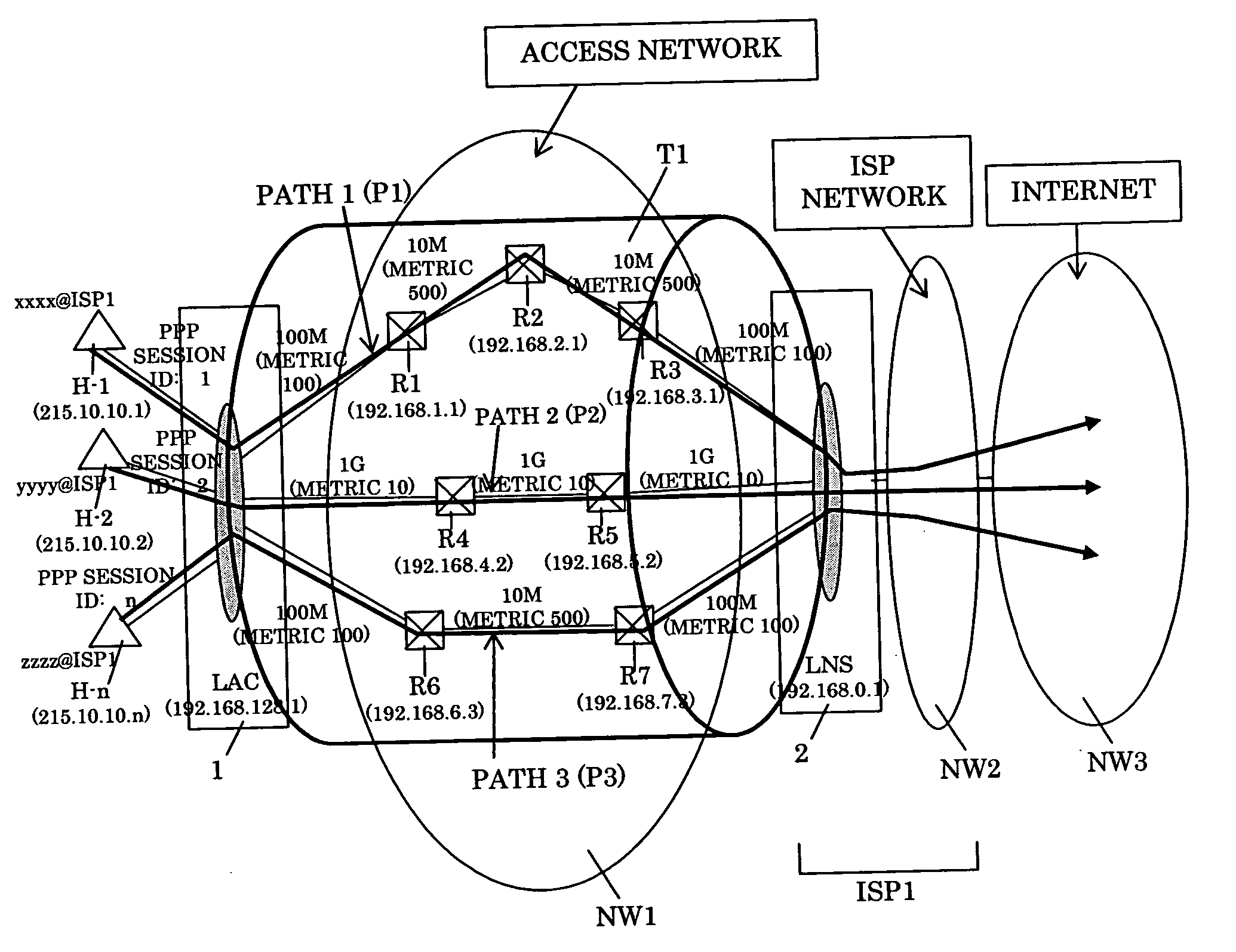
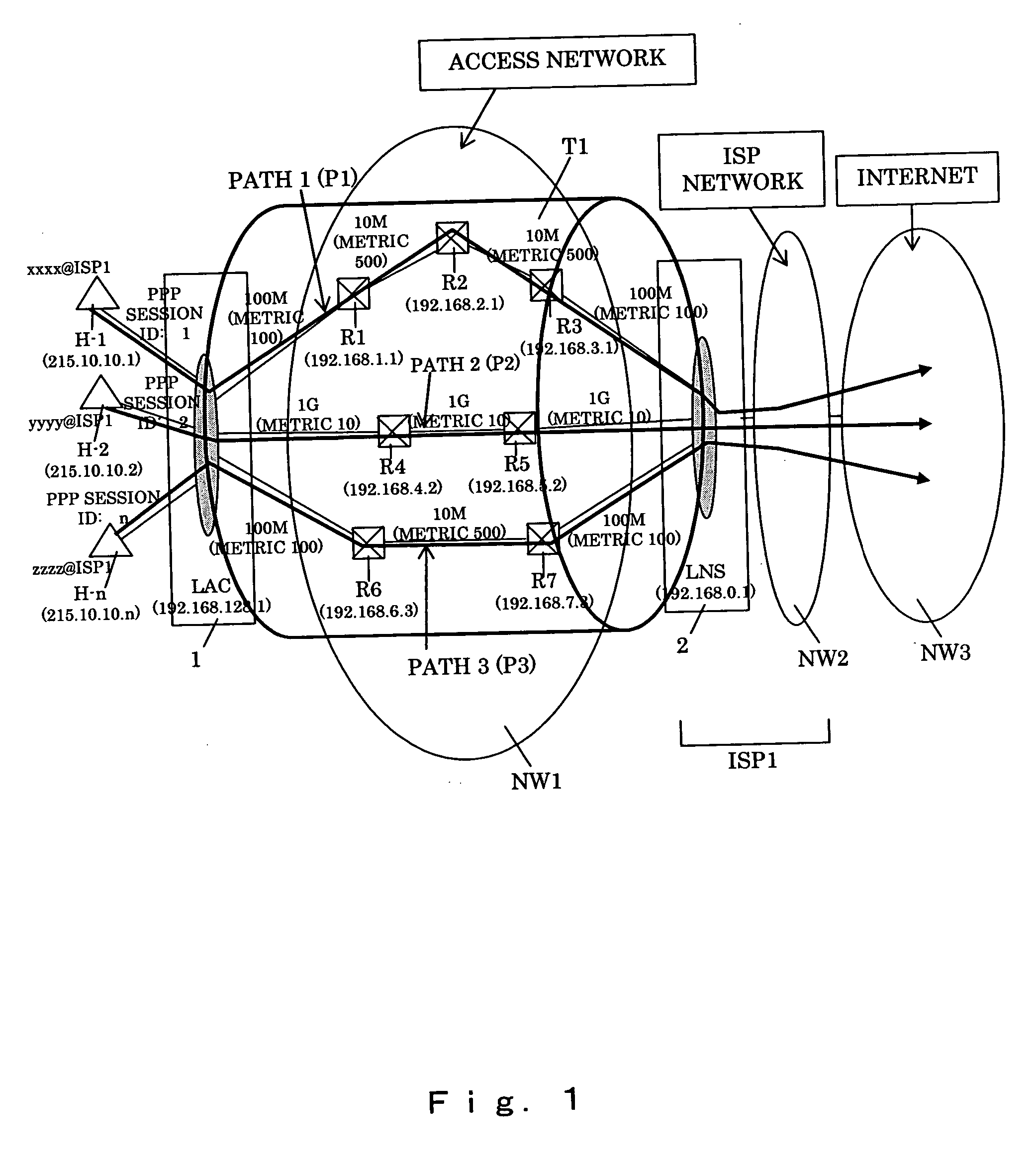
[0068]FIG. 1 shows the configuration of a communication system of a first embodiment.

[0069] The figure shows that hosts H-1, H-2, and H-n access Internet NW3 through access network NW1 and ISP network NW2. First, host H-1, H-2, or H-n accesses Internet service provider ISP1 which the host subscribes to, and gets authenticated as a user. The communication carrier and ISP1 allow LNS (2) and LAC (1), which is a user-side terminating apparatus, to form L2TP tunnel T1 in access network NW1 and LNS (2) to perform user authentication and others.

[0070] An IP address management system in this network will be described next.

[0071] Hosts H-1, H-2, and H-n, routers in ISP network NW2, and network apparatuses in Internet NW3 are managed by their global IP addresses. For instance, host H-1 is assigned a global IP address 215.10.10.1.

[0072] Apparatuses in access network NW1 are managed by their private IP addresses. For instance, router R1 is assigned a private ...


PUM


Abstract

A packet transfer apparatus which can switch a communication path for each of a plurality of users using the same L2TP tunnel is provided. Packet transfer apparatuses terminating L2TP contain a table specifying a flow threshold level and a priority level of each subscriber; the amount of packet flow of each subscriber is measured in accordance with the information in the table; if the threshold level is exceeded, the packet communication path is switched in accordance with the priority level specified for each subscriber. The OSPF protocol is used to manage the path information, and the information of a plurality of paths to a destination is stored in a path management table. The path is switched by specifying destination routers with the source routing option in the IP header of a packet after L2TP encapsulation.

Description

BACKGROUND OF THE INVENTION [0001] 1. Field of the Invention [0002] The present invention relates to packet transfer apparatuses, and more specifically, to a packet transfer apparatus which terminates Layer 2 Tunneling Protocol (L2TP) at a subscriber side or at an Internet service provider (ISP) side. [0003] 2. Description of the Related Art [0004] One known method uses Point-to-Point Protocol (PPP) to authenticate a subscriber as a user when a subscriber terminal is connected via an ISP to the Internet. [0005] PPP is a protocol for making a one-to-one connection between a subscriber terminal and an ISP access point. PPP was originally used in an environment where a terminal is connected directly to an ISP access point by dialup connection through a phone line, authenticated, and then connected to the Internet. [0006] As continuous access to the Internet has become common, the connection between the subscriber terminal and the ISP server is currently made through an access carrier n...

Claims


Application Information

Patent Timeline
IPC IPC(8): H04L12/28H04L12/46H04L45/125H04L47/765
CPCH04L12/2856H04L12/2859H04L12/4633H04L45/00H04L69/168H04L45/34H04L45/66H04L69/16H04L45/30
Inventor OTA, MIGAKUMIYATA, HIROAKINAKAJIMA, JUNSAKAMOTO, YOSHITAKA
Owner HITACHI LTD
Why Eureka
Try Eureka