

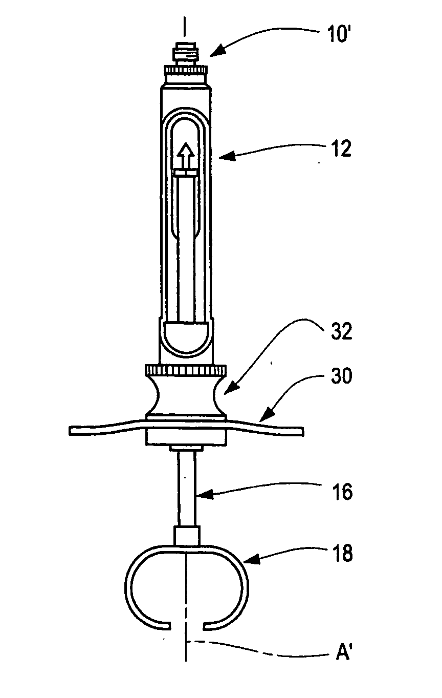
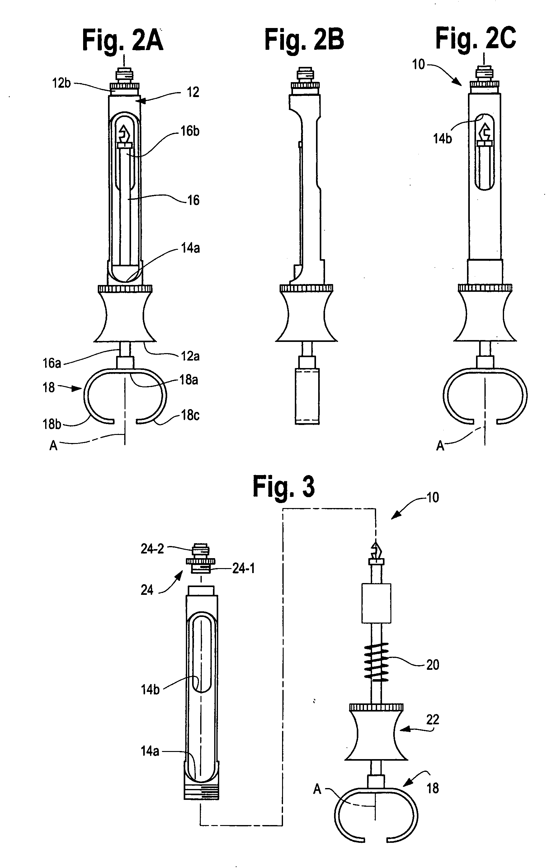
Syringe with split/adjustable thumb ring
a syringe and thumb ring technology, applied in the field of dental syringes, can solve the problems of dental practitioners' hands being uncomfortable, many people, and small hands,
- Summary
- Abstract
- Description
- Claims
- Application Information
AI Technical Summary
Benefits of technology
Problems solved by technology
Method used
Image

Examples
Embodiment Construction
[0016] While embodiments of this invention can take many different forms, specific embodiments thereof are shown in the drawings and will be described herein in detail with the understanding that the present disclosure is to be considered as an exemplification of the principles of the invention and is not intended to limit the invention to the specific embodiment illustrated.
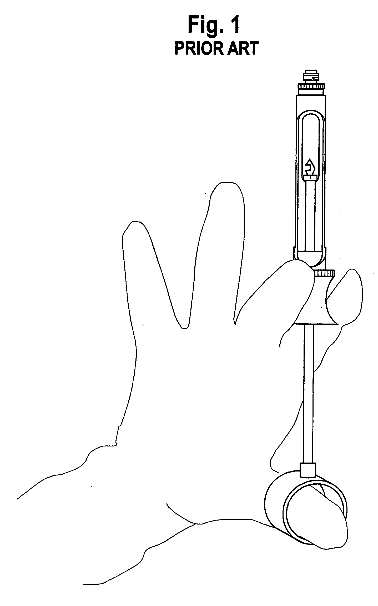
[0017] A syringe that embodies the present invention accommodates a growing number of clinicians with small hands. Historically, aspirating syringes were designed with the idea that “one size fits all”. Generally, this was true at a time when most clinicians were male with male size hands. They performed all of the procedures requiring aspirating syringes.
[0018] With more women becoming dentists, and Hygienists being licensed to administer anesthetics, there has been a continuing need for a small syringe, able to use a standard 1.8 ml cartridge.
[0019] When aspirating with a syringe, the clinician is required ...
PUM
 Abstract
Description
Claims
Application Information