Domestic gas cooker burner
A gas cooker and burner technology, applied in the direction of gas fuel burners, burners, combustion methods, etc., can solve the problems of aggravating burner corrosion, reducing burner service life, and dirt accumulation, so as to reduce CO emissions and load Uniform distribution and improved thermal efficiency
- Summary
- Abstract
- Description
- Claims
- Application Information
AI Technical Summary
Problems solved by technology
Method used
Image
Examples
Embodiment 1
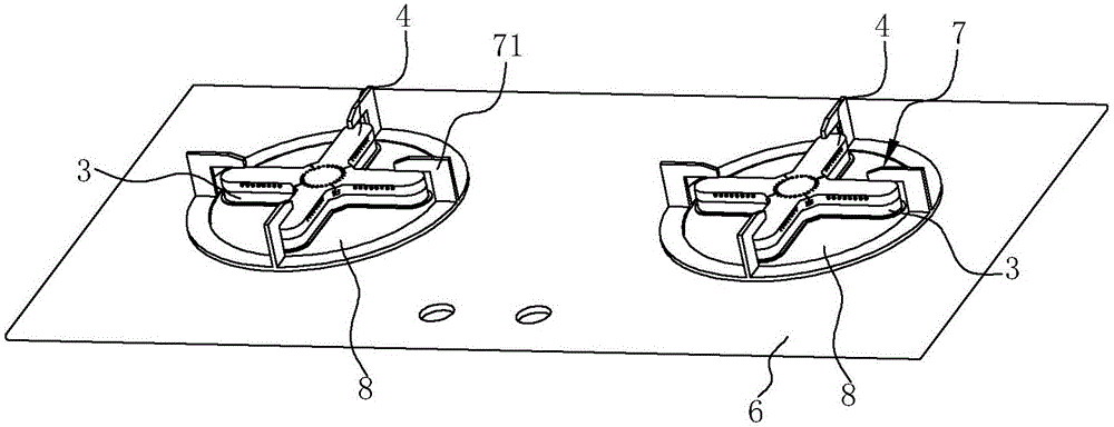
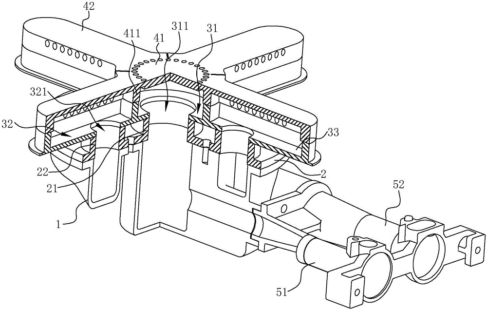
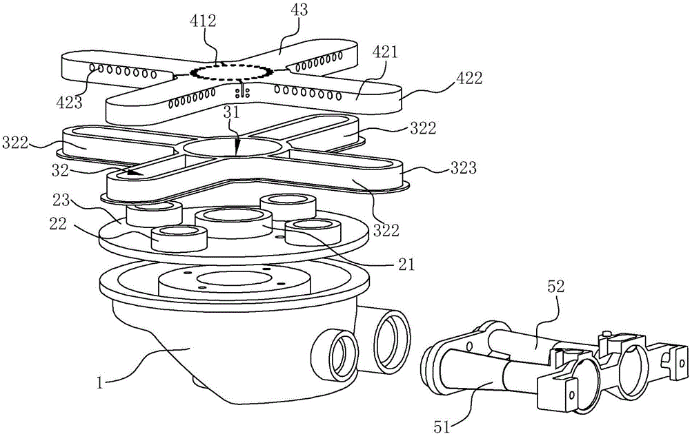
[0028] see Figure 1 ~ Figure 4 , a household gas cooker burner, comprising a base 1, a base cover 2 sequentially arranged above the base 1, a gas mixing seat 3 and a fire cover 4, and an injection pipe, which is used to introduce gas, and the Gas and primary air are fully mixed according to a certain ratio to achieve full combustion effect.
[0029] The base 1 communicates with the injection tube, and the mixed gas introduced by the injection tube enters the base 1 , and the injection tube includes an inner injection tube 51 and an outer injection tube 52 .
[0030] The base cover plate 2 covers the top of the base 1, the base cover plate 2 includes a cover plate 23, and an inner gas channel 21 and an outer gas channel 22 arranged on the cover plate 23, the inner gas channel 21 and the inner injection pipe 51 The outer gas channel 22 communicates with the outer injection pipe 52 . In this embodiment, both the inner gas passage 21 and the outer gas passage 22 are hollow cyli...
Embodiment 2
[0038] see Figure 5 , In this embodiment, the difference from the first embodiment above is that the inner ring fire holes 412 are evenly distributed in a certain circular area of the inner ring fire cover 41 on the top wall 43 . The fire hole adopts this distribution method, the diameter of the fire hole is 1.0-1.4mm, the total area of the fire hole is large, avoiding tempering, can improve the primary air coefficient, and burn stably, the depth of the fire hole is not more than 2mm, preferably Between 0.5mm and 1.5mm, to avoid blockage of the fire hole in case of overflow, etc., and at the same time, it is easy to clean.
Embodiment 3
[0040] see Figure 6 , in this embodiment, the difference from the second embodiment above is that the second side wall 411 of the inner ring fire cover 41 is higher than the first side wall 421 of the outer ring fire cover 42, and at this time the top of the inner ring fire cover 41 The part of the wall 43 and the part of the top wall 43' of the outer ring fire cover 42 are no longer integrated, and the part of the top wall 43 is higher than the part of the top wall 43'. This can make the inner ring fire hole 412 closer to the bottom of the pot. In order to prevent the bottom of the pot from touching the fire cover 4 when using a pointed pot bottom, the second side wall 411 of the inner ring fire cover 41 is higher than the outer ring fire cover 42 The height of the first side wall 421 is not more than 15mm.
PUM
 Abstract
Description
Claims
Application Information
 - R&D
- Intellectual Property
- Life Sciences
- Materials
- Tech Scout
- Unparalleled Data Quality
- Higher Quality Content
- 60% Fewer Hallucinations
Browse by: Latest US Patents, China's latest patents, Technical Efficacy Thesaurus, Application Domain, Technology Topic, Popular Technical Reports.
© 2025 PatSnap. All rights reserved.Legal|Privacy policy|Modern Slavery Act Transparency Statement|Sitemap|About US| Contact US: help@patsnap.com


