Passenger protection device

a technology for protecting devices and passengers, applied in the direction of pedestrian/occupant safety arrangements, process and machine control, instruments, etc., can solve problems such as total failure of devices, sensor failure, and functionality may remain inta

Inactive Publication Date: 2005-09-22
ROBERT BOSCH GMBH
View PDF2 Cites 5 Cited by
  • Summary
  • Abstract
  • Description
  • Claims
  • Application Information

AI Technical Summary

Benefits of technology

[0004] In an example embodiment of the present invention, the failure of one sensor of a device for vehicle occupant protection may be taken into account in each phase of the deployment algorithm. This may prevent a to...

Problems solved by technology

These sensors may fail.
Failure of even one sensor may cause a total failure of the device.
In one example embodiment, due to the greater complexity of current restraint systems,...

Method used


Image

  • Passenger protection device
  • Passenger protection device

Examples


Embodiment Construction

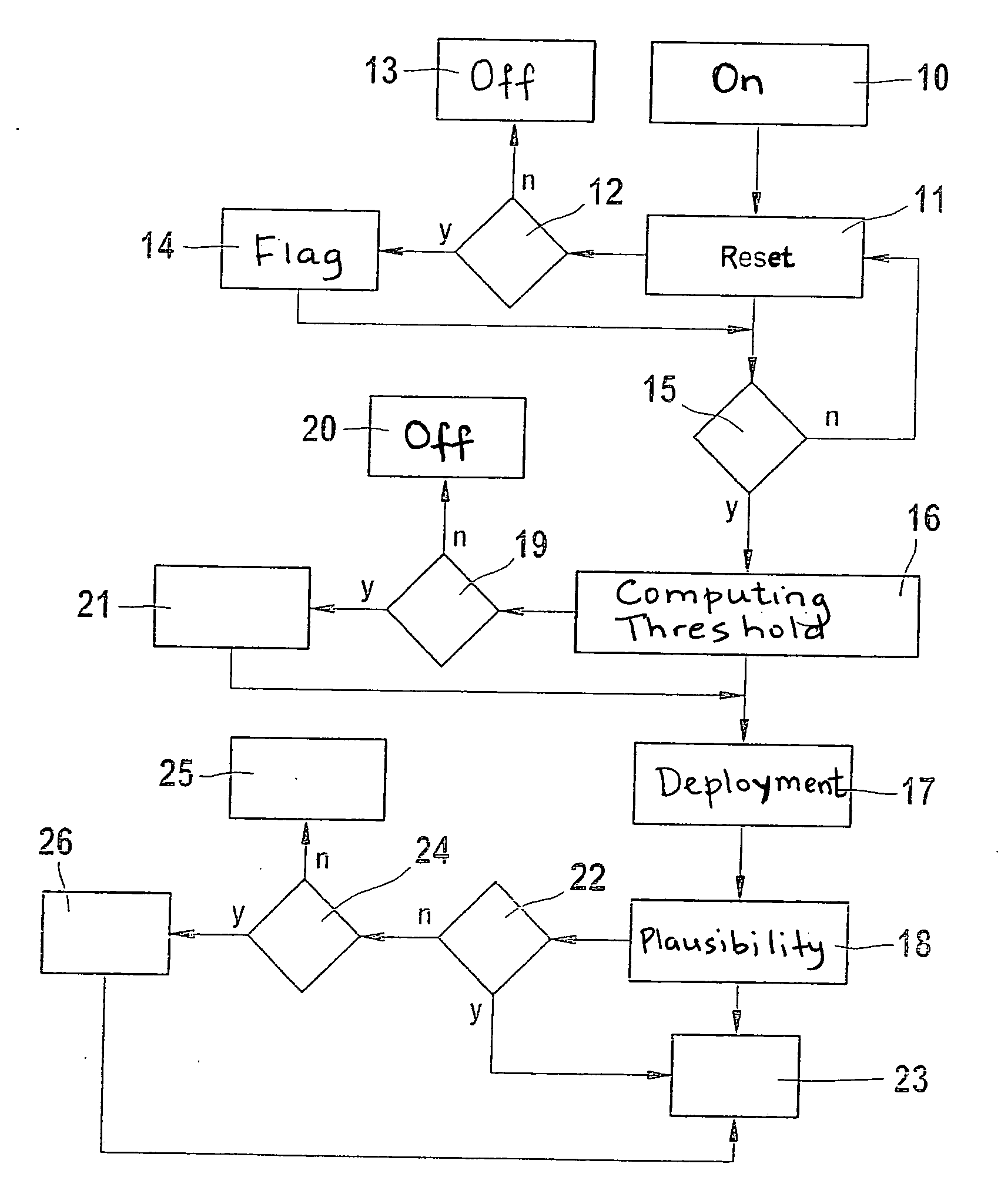
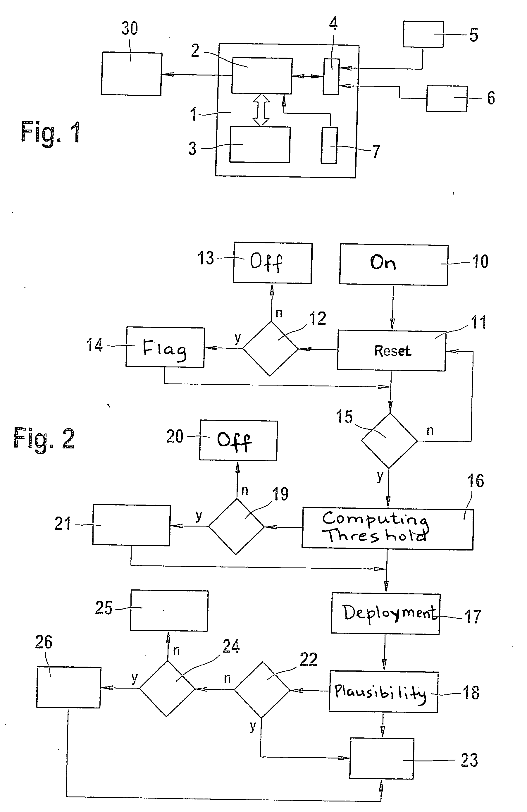
[0012] In an embodiment of the present invention, a device for vehicle occupant protection may have a general response sequence in the event of sensor failures. The point in time of the sensor failure may be considered. The algorithm for computing the deployment of a restraint system may have different phases. A crash event may be anticipated in a first phase or the normal operation, also referred to as the reset state. The signals may be greater in a second phase of the threshold value computation than in normal driving situations, and the deployment algorithm may compute the deployment conditions from the signals. A comparison between the deployment conditions and the sensor signals may be executed in the deployment decision phase. In order to achieve greater reliability for the deployment of a restraint system, a plausibility check of the deployment condition may be executed in the plausibility phase using information from another sensor. An adapted strategy regarding the failure...


PUM


Abstract

A device for vehicle occupant protection. A processor connectable to at least two sensors may execute a deployment algorithm, and, in response to a failure of at least one of the sensors, may alter a sequence of execution of the deployment algorithm according to a point in time of the failure.

Description

FIELD OF THE INVENTION [0001] The present invention is directed to a device for vehicle occupant protection. BACKGROUND INFORMATION [0002] A device for vehicle occupant protection may include sensors. For example, restraint systems having distributed sensors for frontal crash detection are recently being used in greater numbers. In order to obtain more information about the crash severity very early, sensors are installed in the actual crash zone. The side crash detection system needs such external sensors in the crash zone or in its proximity to actually be able to detect a side impact quickly enough. The trend in larger vehicles is to install more than one sensor per side. These sensors may fail. Failure of even one sensor may cause a total failure of the device. [0003] An aspect of the present invention is to prevent a total failure of a device in the event of failure of an individual sensor or even a plurality of sensors. SUMMARY [0004] In an example embodiment of the present in...

Claims


Application Information

Patent Timeline
IPC IPC(8): B60R21/16B60R21/01B60R21/0132B60R21/0136
CPCB60R21/013B60R21/0132B60R2021/0119B60R2021/01122B60R21/0136
Inventor KOEHLER, ARMINROELLEKE, MICHAEL
Owner ROBERT BOSCH GMBH
Why Eureka
Try Eureka