Machine for bending rod-shaped or tubular workpieces

a technology for which is applied in the field of tubular workpieces and workpieces machines, can solve the problems of occupying more space than desired, a relatively large width of clamping devices, and a complicated structure, so as to achieve compact and space-saving design, simplify the design of bending devices, and improve the effect of compact construction

Inactive Publication Date: 2005-09-29
WAFIOS AKTIENGES
View PDF1 Cites 18 Cited by
  • Summary
  • Abstract
  • Description
  • Claims
  • Application Information

AI Technical Summary

Benefits of technology

[0023] Yet another preferred embodiment of the present invention also consists in having both the bending mandrel and the clamping jaw of the tensioning block designed in the form of a roller with a guide groove to be placed in contact with the facing side of the workpiece to be bent, which again results in a simplified design of the bending device according to the present invention, with an especially compact construction. If the wrinkle smoother, again preferably, then has at least two pressure rollers (instead of the sliders) arranged in sequence in the feed direction of the workpiece to be bent, a bending apparatus according to the present invention is then produced with which it is also possible to produce the desired bend in the coiling process. Depending on the position of the roller of the tensioning block relative to the bending mandrel, the bending radius produced in the workpiece can be changed continuously by the clamping device, which makes it possible to produce elliptical, oval or spiral-shaped bends.
[0024] Any suitable shape of bending mandrel can be used in the bending apparatus according to the present invention, such as e.g. in the shape of a circular roller with a corresponding circumferential forming groove. But it is especially preferred for the bending mandrel to be designed such that when viewed parallel to its pivoting axis it has a shape that is not rotationally symmetrical, but is symmetrical to a central axis that is perpendicular to the axis of rotation and passes through it, whereby the forming groove on the bending mandrel, for contacting one side of the workpiece to be bent, viewed relative to this longitudinal central axis, is also positioned symmetrically on both sides of the bending mandrel. One such embodiment results in an especially preferably usable bending mandrel that does not have to be rotated by some 180°, even when changing the bending direction, but rather only by a small angle. On the whole, the bending device according to the present invention is of very compact and space-saving design; it can be used readily for both right-hand and left-hand bending, while still always preserving the advantage that the rotary shafts for the bending mandrel, conversion transmission and clamping device can bring about the corresponding motions of these individual devices through pure rotary motions, and about a common central axis as well (because of the concentrically positioned transmission shafts). This permits especially rapid and precise control of the individual motions, independent of one another.
[0025] The bending device according to the present invention is constructed very compactly and permits great freedom of bending, namely both small intervals between successive bends and small intervals from the bends to the ends of the prefabricated pipe workpieces, making it possible to ensure gentle material handling. At the same time, the possibility also exists of constructing the utilized bending dies in multiple stages, so as to be able to form both different bending radii and pipe material of different diameters with a single die. The many degrees of freedom of the apparatus realized in the invention enable optimal adjustability to the particular circumstances, such as e.g. the pipe diameter, wall thickness, material, and bending radius.

Problems solved by technology

This requires geometrically that the corresponding forming grooves, as well as the fittings on the bending mandrel, must also be adjacent to one another, which results in a complicated structure and a relatively great width of the clamping device, but which is not favorable in view of the desired compact construction of such bending devices.
This too takes up more space than desired.

Method used


Image

  • Machine for bending rod-shaped or tubular workpieces
  • Machine for bending rod-shaped or tubular workpieces
  • Machine for bending rod-shaped or tubular workpieces

Examples


Embodiment Construction

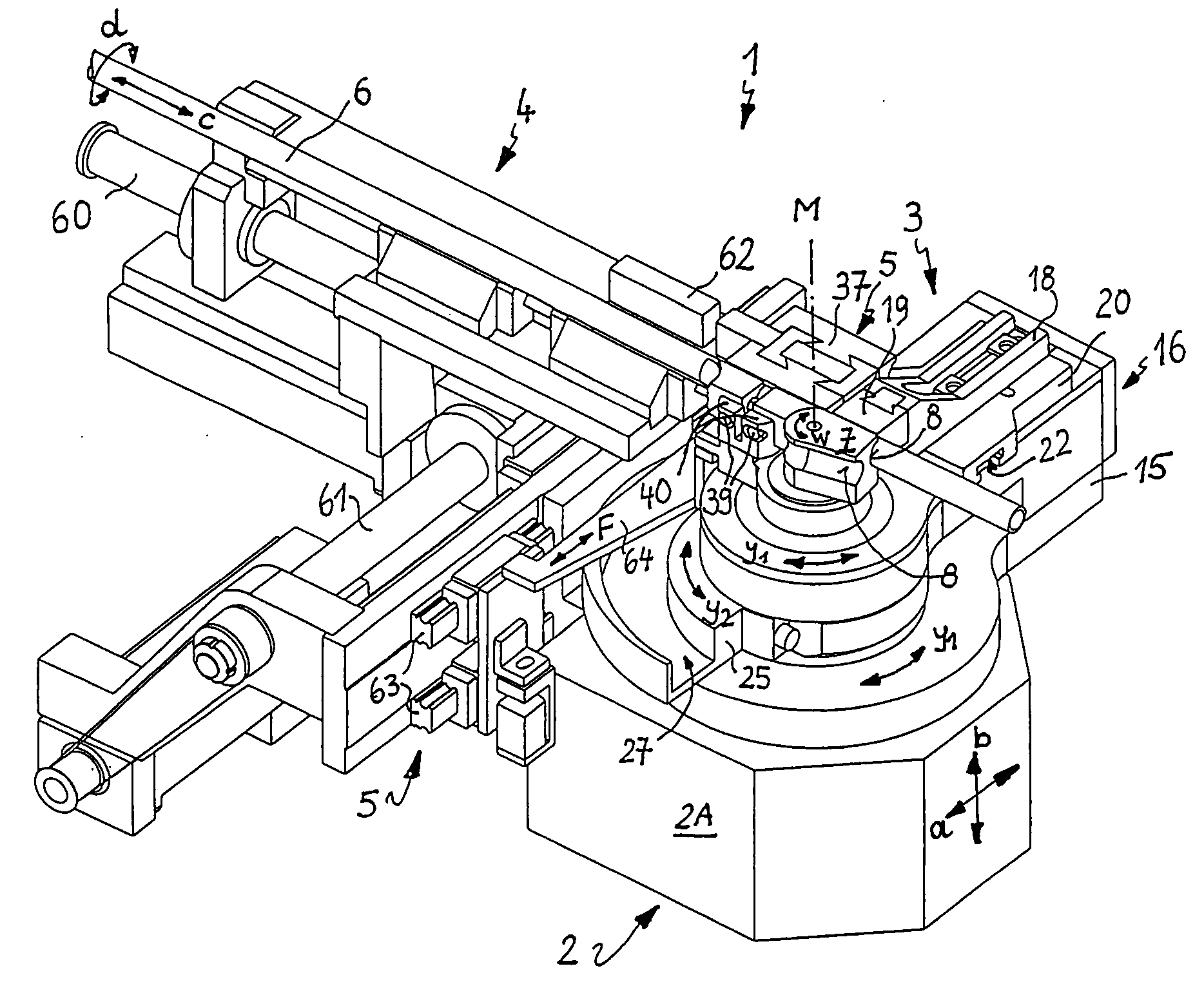
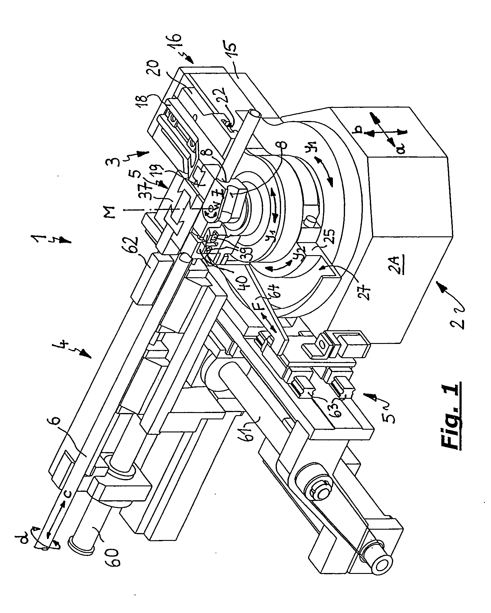
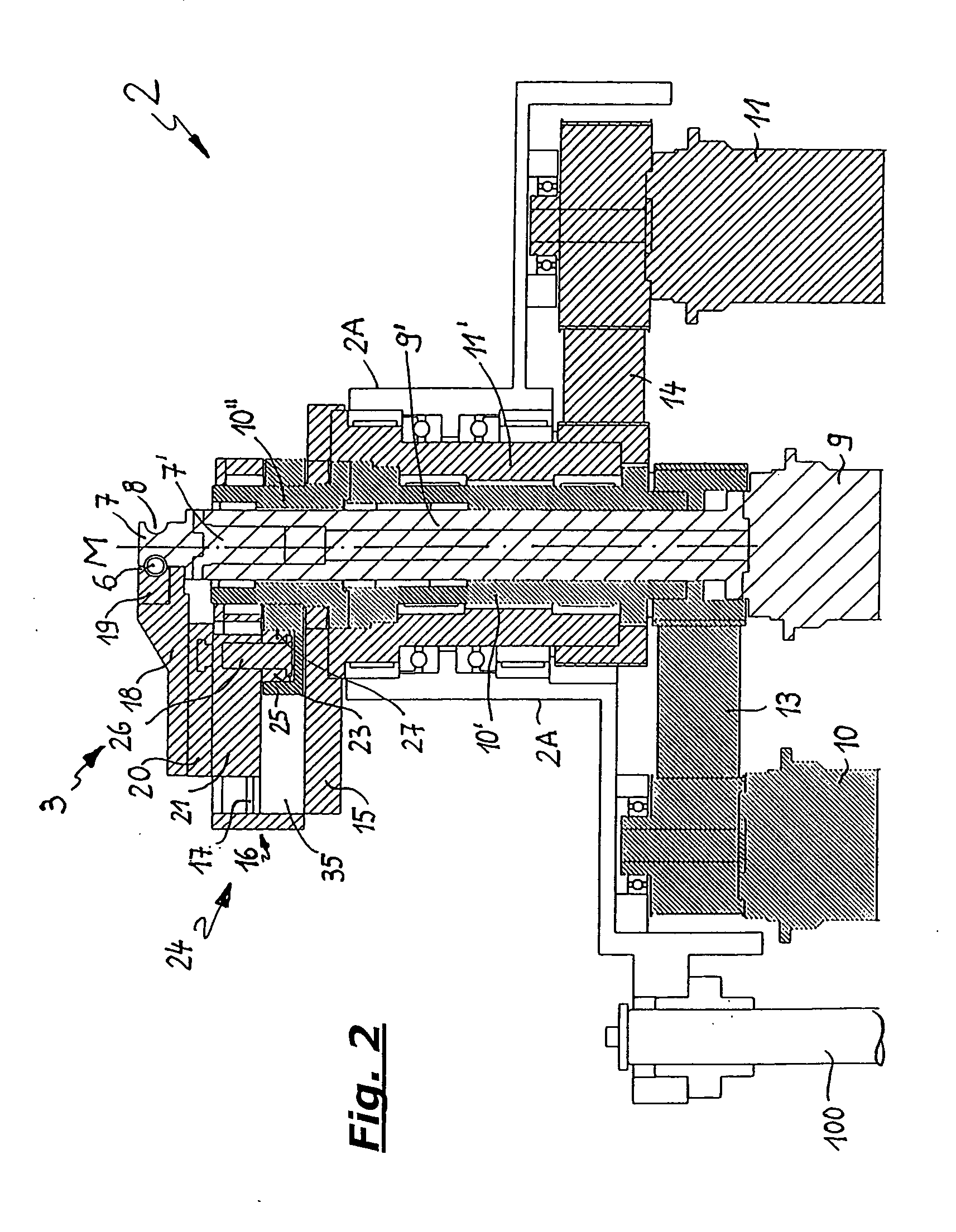
[0041] In the following description of the figures, the portrayals in FIGS. 1 through 12 refer to a first, especially advantageous embodiment of a bending device, while FIG. 13 portrays (in oblique perspective view) a different embodiment of a bending head on such a bending apparatus, and FIG. 14 is a top view showing the principle of yet another embodiment of a bending head. In all of the figures, including when they relate to modified embodiments, the same reference symbols are used for the same parts.

[0042] We will first examine FIGS. 1 through 12, which portray a first embodiment of a bending apparatus.

[0043]FIG. 1 shows a perspective view (obliquely from in front and above) of a bending device 1 shortly before a right-hand bend is executed, while FIG. 12 shows the same oblique perspective portrayal of the same bending apparatus 1, but in the starting state before a left-hand bending procedure.

[0044] As can be seen from FIG. 1, bending device 1 includes essentially three impo...


PUM

PropertyMeasurementUnit
angleaaaaaaaaaa
distanceaaaaaaaaaa
shapeaaaaaaaaaa

Abstract

On a machine for bending rod-shaped or tubular workpieces, which includes a bending head having a bending mandrel mounted on a rotational axis and rotatable by means of a rotary drive, and having a clamping device for pressing the workpiece to be bent against a forming groove on the bending mandrel and also a feeding device for the workpiece to be processed, whereby the clamping device is positionable relative to the bending mandrel and can is also pivotable concentrically to the rotational axis of the bending mandrel, the clamping device is attached to two mutually independent rotary drives, one of which performs its pivoting movement about the rotational axis of the bending mandrel, and via the other of which it can be moved with respect to the bending mandrel by using an interposed conversion transmission that converts a rotary motion to a linear motion, whereby the bending head includes three concentrically nested rotary shafts for transmitting the drive of the three rotary drives to the bending mandrel, to the conversion transmission and to the clamping device, each of which is connected to one of the rotary drives.

Description

FIELD OF THE INVENTION [0001] The present invention relates to a machine for bending rod-shaped or tubular workpieces, whereby the bending apparatus includes a bending head having a bending mandrel mounted on a rotational axis and rotatable by means of a rotary drive, and having a clamping device for pressing the workpiece to be bent against a forming groove on the bending mandrel, whereby the bending head also has a feeding device for the workpiece to be processed, and the clamping device is positionable relative to the bending mandrel and is also pivotable concentrically to the rotational axis of the bending mandrel. BACKGROUND OF THE INVENTION [0002] Such bending apparatus are used in modern bending machines for rod-like workpieces and for prefabricated conduits primarily having larger cross sections. [0003] In such cases the bending apparatus constitutes a plurality of units whose interaction makes good bending results possible, especially in the case of tubular workpieces with ...

Claims


Application Information

Patent Timeline
Patent Type & Authority Applications(United States)
IPC IPC(8): B21D7/024B21D7/04
CPCB21D7/024
Inventor MAIER, WERNERWOLF, JURGENHACKER, FRANKSCHLUND, PATRICKGEISEL, DIETERSAUTTER, DIETMAR
Owner WAFIOS AKTIENGES
Why Eureka
Try Eureka