Method for operating tests of vibration level switch sensors and corresponding vibration level switch

a technology of vibration level switch and sensor, which is applied in the direction of geological measurements, liquid/fluent solid measurements, capacity measurement calibration, etc., can solve the problems of rough changes of the sensor, the method of testing the functioning is only suitable, and the inability to test the sensor mechanism

Active Publication Date: 2005-09-29
VEGA GRIESHABER GMBH & CO
View PDF5 Cites 18 Cited by
  • Summary
  • Abstract
  • Description
  • Claims
  • Application Information

AI Technical Summary

Benefits of technology

[0013] Thus, according to the inventive operating test method, the same mechanical, electrical, and electronic sensor components can be used for normal level detection operation as are used in the operating tests itself. Moreover, the entire signal chain can be incorporated into the test. The sensor is measured in the range of its operational resonance point and is thus very realistic, also with respect to surrounding vibrations and electromagnetic scattering. Due to the high signal amplitude available, it is also relatively failure-resistant. This is a great advantage with respect to operating test methods, exciting the sensor outside its operating resonance range. Due to the very small oscillation amplitudes, which are obtainable thereby, external vibrations and electromagnetic scattering could simulate totally changed sensor characteristics.
[0022] In another aspect of the invention it is provided for the operating test to be carried out automated cyclically. Another possibility is that the operating test is initiated by external input of a test command. An advantage is that the same signal processing blocks, which are used for the carrying out of the operating test, are also used for measuring the level in a container.

Problems solved by technology

However, this method for testing the functioning is only suitable for liquid level switch sensors analyzing the frequency.
A testing of the sensor mechanism is not possible.
However, only very rough changes of the sensor can be detected by this method.
However, with this sensor, no operating tests are possible at all.

Method used


Image

  • Method for operating tests of vibration level switch sensors and corresponding vibration level switch
  • Method for operating tests of vibration level switch sensors and corresponding vibration level switch
  • Method for operating tests of vibration level switch sensors and corresponding vibration level switch

Examples


Embodiment Construction

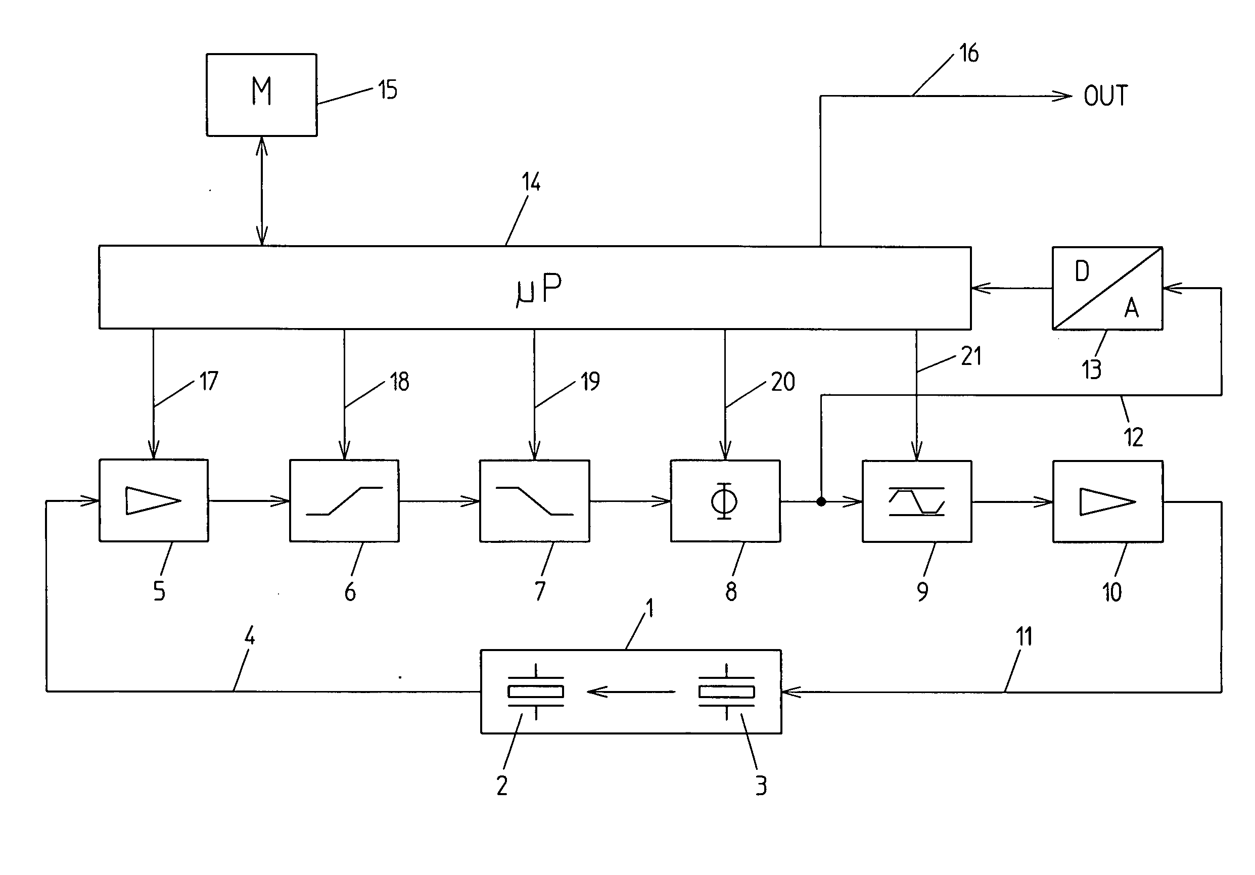
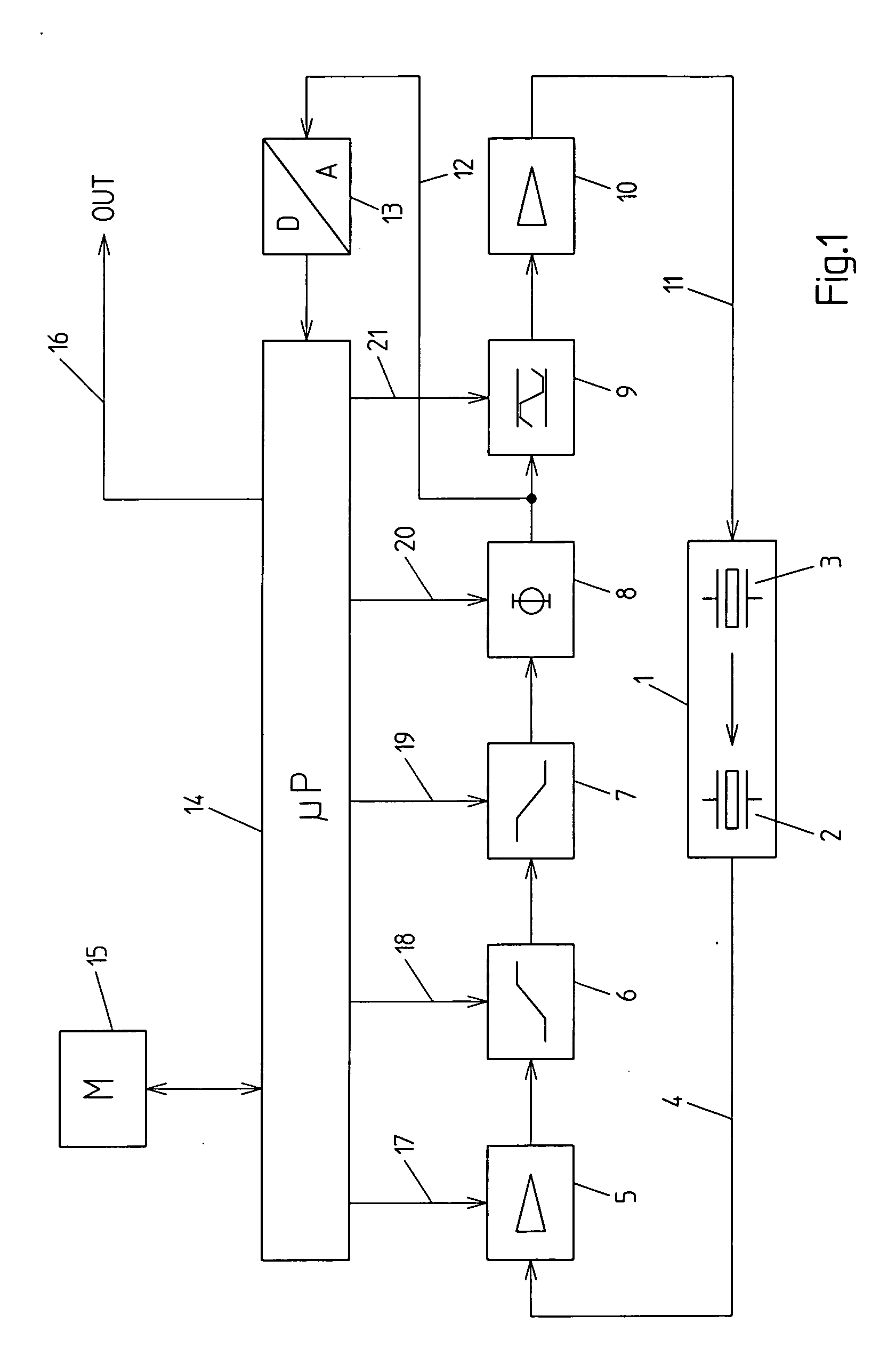
[0034]FIG. 1 shows a schematic diagram of the inventive vibration level switch system. First, the normal functioning for a measurement of the inventive sensor arrangement is described without an operating test being carried out.

[0035] Vibration resonator 1, being realized as a tuning fork, is dipped into the liquid or solid bulk material to be measured. For excitation and detection of mechanical oscillations, resonator 1 is equipped with an electromechanical converter system, comprising a piezo-electric oscillation detection crystal 2 and an oscillation excitation crystal 3. The electrical output signal 4 of detection crystal 2 is supplied to blocks 5 to 10, forming an oscillation exciting feedback circuit. A second output signal, which is the processed first output signal, namely output signal 11, serves for controlling excitation crystal 3. By means of the signal filter and amplification effect of the feedback circuit, a self-preserving oscillation of the vibration resonator 1 on...


PUM

PropertyMeasurementUnit
data processingaaaaaaaaaa
frequencyaaaaaaaaaa
resonance frequencyaaaaaaaaaa

Abstract

A method for carrying out operating tests of vibration level switches for liquids or solid bulk material or mixtures thereof is provided, whereby a vibration resonator (1) of a level detection sensor is excited by an oscillation exciting feedback circuit to oscillate, whereby at least one excitation parameter of a plurality of signal processing blocks (5, 6, 7, 8, 9, 10) of the feedback circuit is varied, and the resulting oscillation change is compared by a microprocessor (14) to datasets comprising data of corresponding oscillation changes of a failure free system. Moreover, a vibration level switch for measuring the level in containers for carrying out the inventive method is provided.

Description

TECHNICAL FIELD OF THE INVENTION [0001] The present invention relates to a method for an operating test of vibration level switches as well as to a vibration level switch, adapted to carry out the operating test. [0002] The invention is applicable to vibration level switches which are employed for measuring solid bulk material as well as vibration level switches which are employed for measuring liquids in containers. BACKGROUND OF THE INVENTION [0003] Vibration level switch systems usually consist of a vibration resonator and an oscillation exiting feedback circuit coupled thereto which during operation of the system excites the vibration resonator to its resonance frequency such that a self-preserving oscillation results. [0004] In prior art, vibration sensors may be known, operating on this principle. For testing the faultless functioning of such a sensor system, instead of the vibration sensor, a band pass filter is connected to the feedback circuit. The generated oscillation fre...

Claims


Application Information

Patent Timeline
Patent Type & Authority Applications(United States)
IPC IPC(8): G01F23/296G01F25/00
CPCG01F23/2967G01N2291/02836G01F25/0076G01F25/24G01F23/80
Inventor RAFFALT, FELIX
Owner VEGA GRIESHABER GMBH & CO
Why Eureka
Try Eureka