
Pre-chambered type spark plug with pre-chamber entirely below a bottom surface of a cylinder head

Inactive Publication Date: 2005-09-29
CATERPILLAR INC
View PDF16 Cites 86 Cited by
  • Summary
  • Abstract
  • Description
  • Claims
  • Application Information

AI Technical Summary

Benefits of technology

[0003] Unlike in a diesel cycle engine, spark ignited engines may also control a combustion event through initiation of a spark. Encapsulated spark plugs have shown an improvement gained from improving conditions and mixing of fuel and air along with an improvement gained by controlling initiation of the spark. The encapsulated spark plug includes a plug shell surrounding an electrode gap. The plug shell defines an ignition chamber separated from a combustion chamber. An orifice or orifices are positioned in the plug shell interconnecting the ignition chamber with the combustion chamber. The ignition chamber and the plug shell separate a flame kernel from turbulence in the combustion chamber. As a piston compresses and air and fuel mixture within the combustion chamber, at least a portion of the air and fuel mixture passes through the orifices into the ignition chamber.

Problems solved by technology

Although the encapsulated spark plug has been shown to increase efficiency and reduce emissions other drawbacks tend to reduce their use.
The encapsulated spark plug which protrudes into the combustion chamber has been know to causes pre-ignition and other detonation problems.
In a lean air and fuel mixture the voltage needed to jump an electrode gap between an electrode and ground electrode required results in an increased voltage due to break down in the voltage.
Further exacerbating wear, the orifices through the plug shell experience extreme temperature changes.
These high velocities increase heat transfer from the hot gases to the plug shell decreasing life of the encapsulated spark plug.
Additionally, resistance such as welds used to attach the plug shell to the plug hinders heat transfer away from the orifices.

Method used


Image

  • Pre-chambered type spark plug with pre-chamber entirely below a bottom surface of a cylinder head
  • Pre-chambered type spark plug with pre-chamber entirely below a bottom surface of a cylinder head
  • Pre-chambered type spark plug with pre-chamber entirely below a bottom surface of a cylinder head

Examples


Embodiment Construction

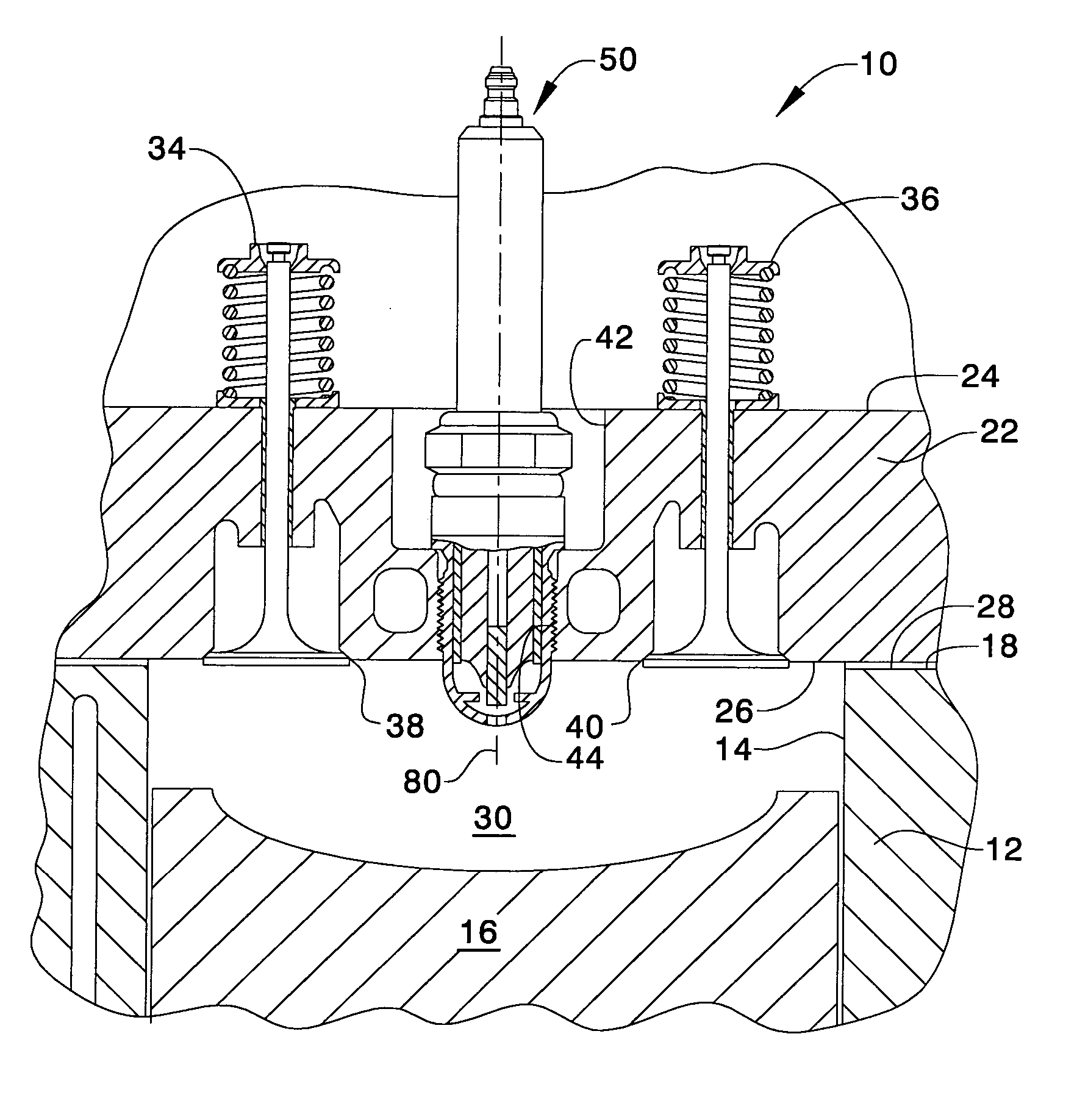
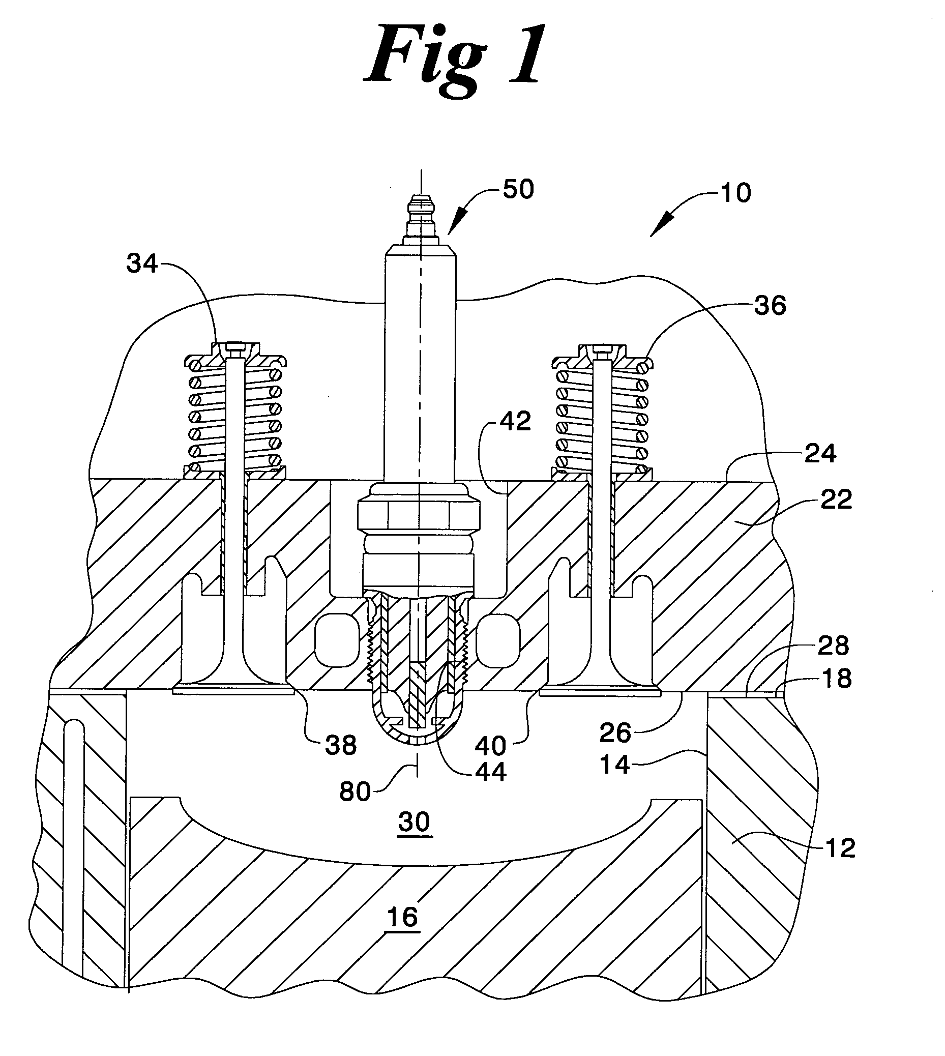
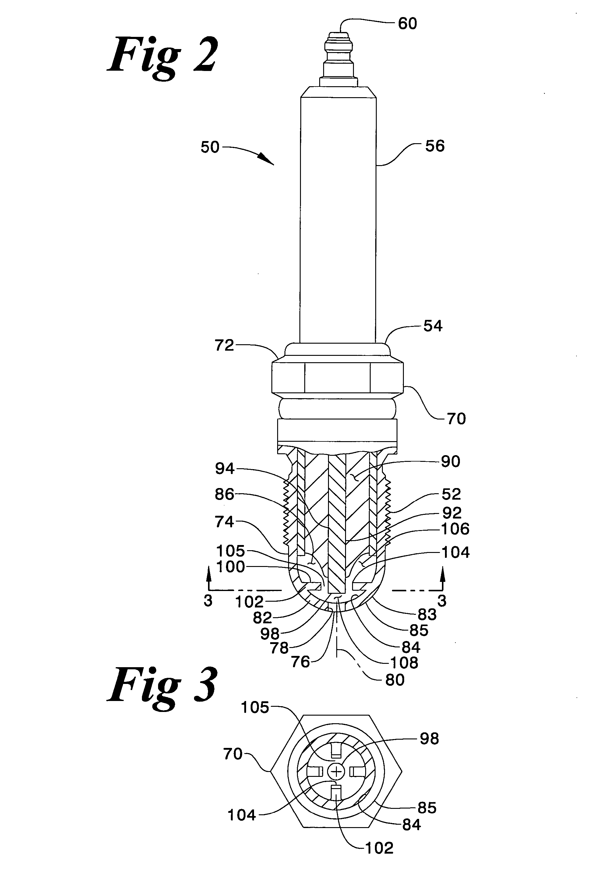
[0017] In FIG. 1, a spark ignition engine 10 is partially shown. The engine 10 includes a block 12 having a cylinder bore 14 therein. A piston 16 of conventional design is movably positioned within the cylinder bore 14 in a conventional manner. The block 12 defines a top surface 18.

[0018] A cylinder head 22 defines a top surface 24 and a bottom surface 26. The bottom surface 26 of the cylinder head 22 is removably attached to the top surface 18 of the block 12 in a conventional manner such as by a plurality of bolts, not shown. A gasket 28 is normally interposed the top surface 18 of the block 12 and the bottom surface 26 of the cylinder head 22. Thus, a combustion chamber 30 is defined between the bottom surface 26 of the cylinder head, the cylinder bore 14 of the block and the piston 16. The cylinder head 22 has at least one intake valve mechanism 34 operatively positioned therein and at least one exhaust valve mechanism 36 operatively positioned therein. An intake sealing portio...


PUM


Abstract

The present spark plug is of the encapsulated design and facilitates the life of the spark plug, enhances the combustion process and reduces emissions. The position of an ignition chamber of the spark plug is substantially within a combustion chamber of an engine. The configuration of a parabolic end forms the ignition chamber, reduces the heat transferred to the spark plug and increases the life of the spark plug. The configuration or design of the spark plug makes the manufacturing process less costly and facilitates the combustion process by using one of a single orifice or a plurality of orifices positioned at and in a preestablished manner. The configuration will reduce or eliminate pre-ignition and other detonation problems enabling the timing to be advanced further reducing emissions.

Description

TECHNICAL FIELD [0001] This invention relates generally to a spark ignition device and more particular to a pre-chamber type spark plug. BACKGROUND [0002] Emissions and efficiency continue to drive technology to improve combustion of air and fuel mixtures. Many improvements control the air and fuel mixture. Examples of some combustion of air and fuel mixtures improvements include improved combustion chamber design, valve porting and fuel or air flow and atomization process. These improvements all generally improve control of the fuel and air mixture. [0003] Unlike in a diesel cycle engine, spark ignited engines may also control a combustion event through initiation of a spark. Encapsulated spark plugs have shown an improvement gained from improving conditions and mixing of fuel and air along with an improvement gained by controlling initiation of the spark. The encapsulated spark plug includes a plug shell surrounding an electrode gap. The plug shell defines an ignition chamber sepa...

Claims


Application Information

Patent Timeline
IPC IPC(8): F02B19/12F02M57/06H01T13/54
CPCF02B19/12Y02T10/125H01T13/54Y02T10/12
Inventor BOLEY, WILLIAM C.WINKLEMAN, BRADY L.SCHULTZ, JAMES M.MUELLER, GARY P.NIETHAMMER, JASON L.
Owner CATERPILLAR INC
Learn More