
Cover supporting structure for light vehicle

a technology for supporting structures and light vehicles, applied in transportation and packaging, cycle equipment, cycle parts, etc., can solve problems such as cover detachedness, and achieve the effect of improving external appearan

Inactive Publication Date: 2005-09-29
HONDA MOTOR CO LTD
View PDF0 Cites 5 Cited by
  • Summary
  • Abstract
  • Description
  • Claims
  • Application Information

AI Technical Summary

Benefits of technology

The invention is a cover supporting structure for a light vehicle that includes a cover that covers a part of a power unit mounted on a frame. The cover is supported by the power unit or a supporting member in multiple locations. The cover is elastically supported by a bolt in at least one location and by an elastic member in each of the remaining locations. The elastic member is fitted into the cover and the power unit or supporting member. The structure makes it easy to attach the cover and prevents deformation of the cover due to fastening. The invention also provides a coming-off prevention means to keep the elastically inserted state of the supporting protrusion in the elastic member, making it difficult for the remaining supporting portions to come off easily. The invention also includes a design that makes the supporting portions difficult to see from the outside, improving the external appearance. The coming-off prevention means can be easily constructed using simple parts.

Problems solved by technology

However, there is a possibility that the cover is detached by a small external force or the like.

Method used


Image

  • Cover supporting structure for light vehicle
  • Cover supporting structure for light vehicle
  • Cover supporting structure for light vehicle

Examples


Embodiment Construction

[0018] A description will be given below of embodiments of the present invention on the basis of examples of the present invention which are shown in the accompanying drawings.

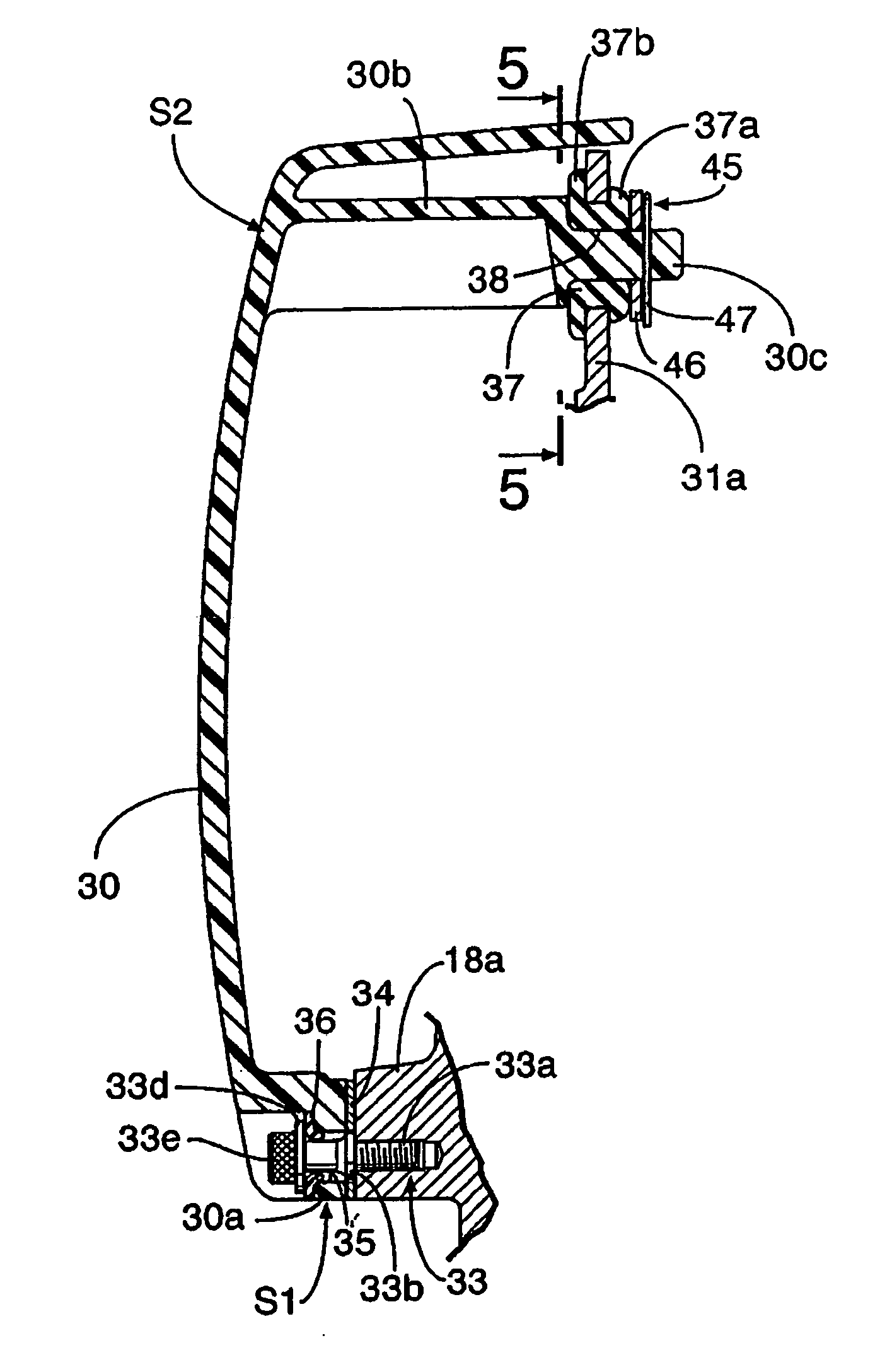
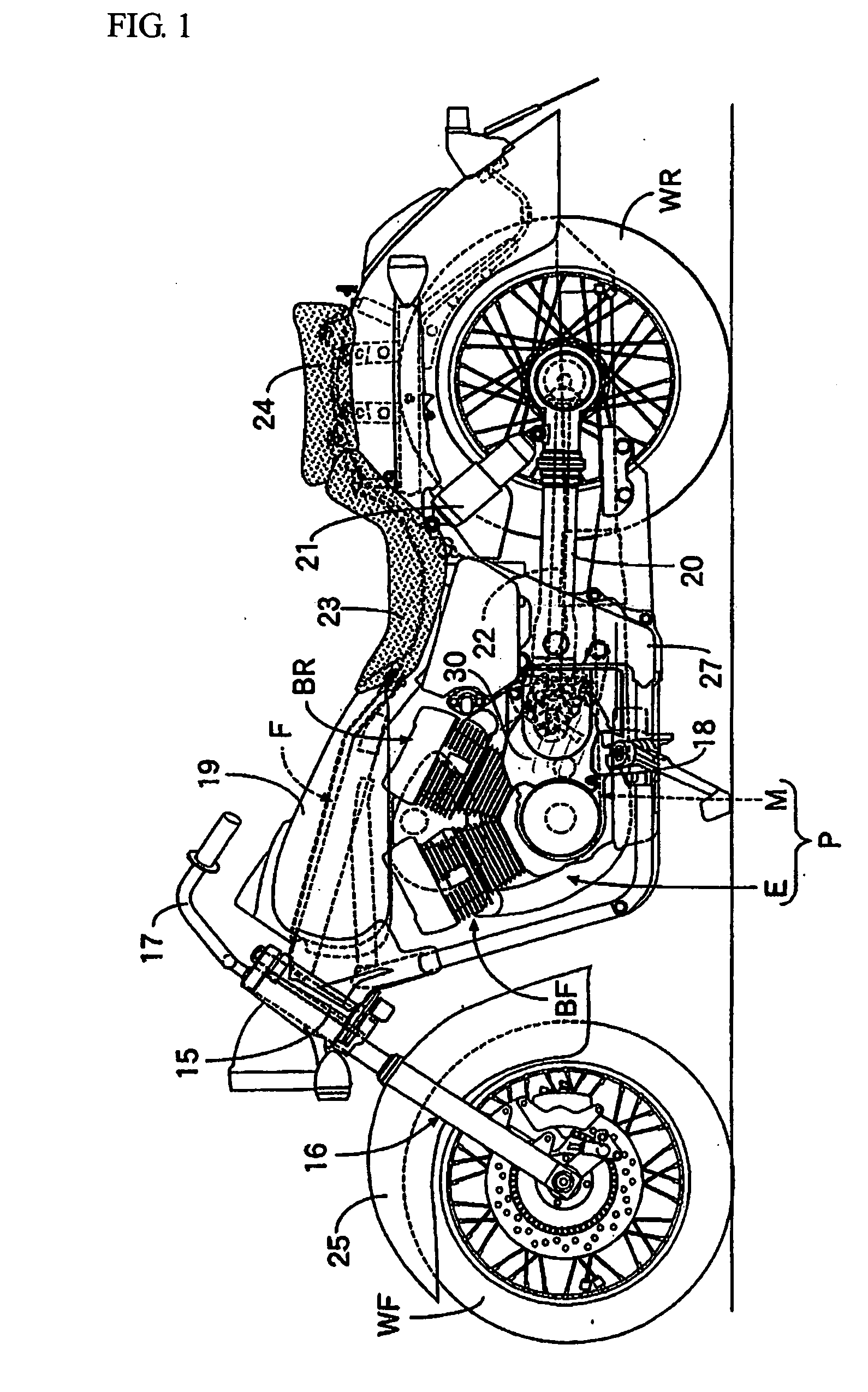
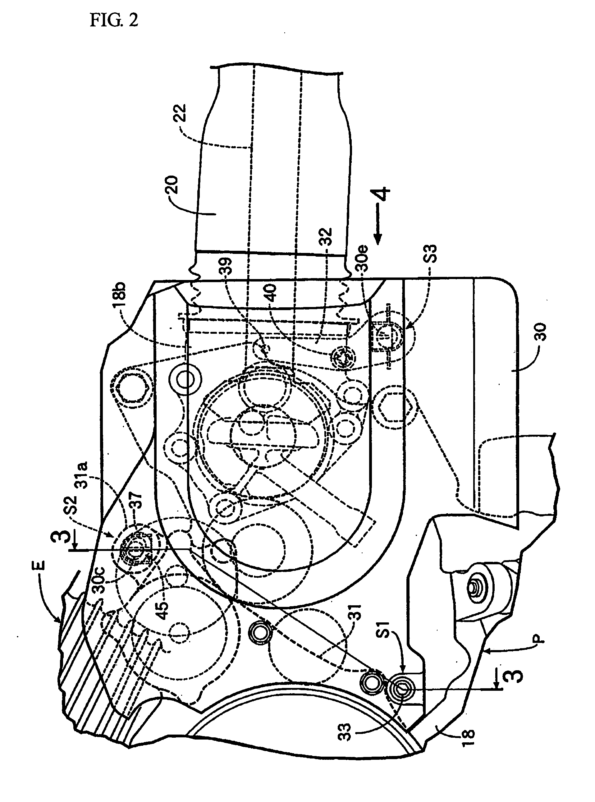
[0019] FIGS. 1 to 5 show a first example of the present invention. FIG. 1 is a side view of a motorcycle. FIG. 2 is a main part enlarged view of FIG. 1. FIG. 3 is a cross section taken along the line 3-3 of FIG. 2. FIG. 4 is a view on the arrow 4 of FIG. 2. FIG. 5 is an enlarged cross section taken along the line 5-5 of FIG. 3.

[0020] First, in FIG. 1, a head pipe 15 provided to the front end of a frame F of the motorcycle, which is a light vehicle, steerably supports a front fork 16, which pivotally supports a front wheel WF, and a steering handle 17 is coupled to the front fork 16. In the front portion of the frame F, a power unit P is mounted, the power unit P being constituted of a V-type engine E, in which a front bank BF and a rear bank BR are arranged in an approximately V-shape, and a transmission M, ...


PUM


Abstract

A cover supporting structure for a light vehicle is provided in which the cover which covers a part of a power unit is supported by the power unit or a supporting member in a plurality of supporting portions.

Description

FIELD OF THE INVENTION [0001] The present invention relates to a cover supporting structure for a light vehicle, in which a cover which covers a part of a power unit mounted on a frame is supported, in a plurality of supporting portions, by the power unit or a supporting member which is disposed around the power unit. BACKGROUND OF THE INVENTION [0002] Japanese Patent Laid-Open No. S59-31589 discloses that a plurality of portions of a cover, which covers a part of a power unit mounted on a frame of a motorcycle which is a light vehicle, are fastened to the power unit or the frame via bolts. Japanese Patent Laid-Open No. 2003-83162 discloses a plurality of engaging protrusions, which are provided to a cover which covers a part of an engine in a power unit, elastically engaged with the engine in a removable manner. [0003] However, when the cover is fastened to the power unit or the peripheral member of the power unit via bolts in a plurality of portions as disclosed in Japanese Patent...

Claims


Application Information

Patent Timeline
Patent Type & Authority Applications(United States)
IPC IPC(8): B62D25/10B62J23/00
CPCB62J23/00
Inventor INUI, HIROATSUTAKEMOTO, KAZUHISA
Owner HONDA MOTOR CO LTD
Learn More